
Coaxial connector and coaxial connector with antenna

A technology of coaxial connectors and connectors, which is applied to parts, connections, and two-part connection devices of connection devices, etc., can solve problems such as cumbersome operations, and achieve the effects of cost reduction, easy manufacture, and simple structure

Inactive Publication Date: 2011-05-04
JST MFG CO LTD
View PDF5 Cites 13 Cited by
  • Summary
  • Abstract
  • Description
  • Claims
  • Application Information

AI Technical Summary

Problems solved by technology

This type of coaxial connector must require the fastening operation of the thread, but this operation is cumbersome, thus, it has been proposed that there is a push-pull type coaxial connector that does not require such an operation (for example, refer to the following Patent Document 1, 2)

Method used


Image

  • Coaxial connector and coaxial connector with antenna
  • Coaxial connector and coaxial connector with antenna
  • Coaxial connector and coaxial connector with antenna

Examples


Embodiment Construction

[0038] Embodiments for carrying out the present invention will be described below with reference to the drawings. However, the implementation forms given below are examples of coaxial connectors used to specifically implement the technical concept of the present invention, and the present invention is not intended to be specified therein, and are equally applicable to the claims included in the claims. other implementation forms.

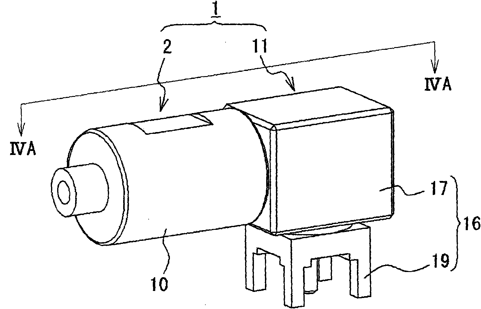
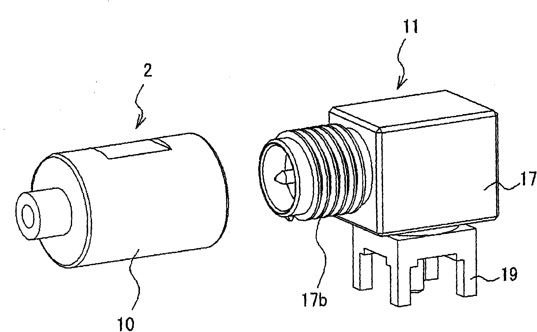
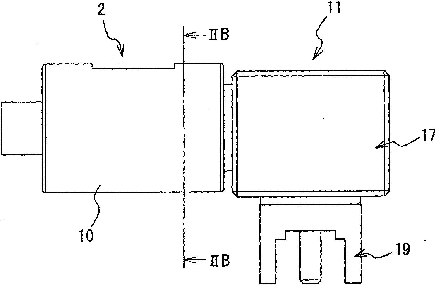
[0039] refer to Figure 1A , B, Figure 2A , B, explain the coaxial connector of the embodiment of the present invention. in addition, Figure 1A , B represents the plug and the socket that constitute the coaxial connector of the embodiment of the present invention, Figure 1A is a perspective view of a state where a plug and a socket are connected, Figure 1B for Figure 1A The perspective view of the disassembled state, Figure 2A for Figure 1A side view of the coaxial connector, Figure 2B for along Figure 2A A cross-sectional view of...


PUM


Abstract

The present invention relates to a coaxial connector and another coaxial connector with an antenna. According to the coaxial connector provided by the invention, one connector is rotated compulsively at an anti-dropping fixing state of a pair of connectors. Therefore the connectors are positioned and fixed with a random angle. The connectors comprise a first connector and a second connector in pair. The first connector comprises the following components: a first core conductor; and a fixing component which accommodates the core conductor. The second connector comprises the following components: a second core conductor which is connected with the first core conductor; a connector housing which accommodates the core connector and is inserted into the fixing component. The fixing component comprises a fixed part and a plurality of fixing fingers. The fixing fingers extend from the fixed part frontward and are respectively provided with a fastening part at the front end. The connector housing comprises a blocking part which is blocked with the fastening part at the inner wall surface and anti-rotation projections for performing rotation prevention of the fixing component. When a random connector is rotated compulsively, the fixing fingers elastically deform and exceed the anti-rotation projections. The connectors are positioned and fixed according to a preset angle.

Description

technical field [0001] The present invention relates to a coaxial connector and a coaxial connector with an antenna. More specifically, the present invention relates to the following coaxial connector and a coaxial connector with an antenna connected to the coaxial connector. A connector, wherein the coaxial connector is composed of a plug and a socket, and when the plug and the socket are connected, any one of them, such as the plug, can be positioned and fixed according to a specified angle. The present invention is especially suitable for the occasion where an L-shaped antenna is installed on a plug. Background technique [0002] Ordinary coaxial connectors consist of a plug and a socket, which are broadly classified according to their connection type: the so-called screw-type type, in which one of the connectors, such as a plug, is screwed to the socket of the other ; The so-called push-pull type, wherein one of them is pressed into the other to fit and connect. [000...

Claims


Application Information

Patent Timeline
Patent Type & Authority Applications(China)
IPC IPC(8): H01R24/38H01R13/639H01Q1/22
Inventor 东地昭博竹岛英树汤川久仁彦辻本将辉
Owner JST MFG CO LTD
Learn More