Method for replacing optical fiber composite overhead ground wire or common overhead ground wire without power cut

An overhead ground wire and optical fiber composite technology, which is applied in the configuration of ground wires, overhead line/cable equipment, etc., can solve the problem that the ground wire is easy to touch the power line, etc., and achieve the effect of reducing the trouble of approval

Inactive Publication Date: 2011-05-04
FUJIKURA HENGTONG AERIAL CABLE SYST
View PDF0 Cites 11 Cited by
  • Summary
  • Abstract
  • Description
  • Claims
  • Application Information

AI Technical Summary

Problems solved by technology

[0003] In order to overcome the shortcomings of existing methods for replacing optical fiber composite overhead ground wires or ordinary overhead ground wires of power transmission lines, and to solve the problem that the ground wire is easy to touch the power line during the process of dismantling the old ground wire and erecting a new ground wire, the present invention provides a The method of replacing the optical fiber composit

Method used


Image

  • Method for replacing optical fiber composite overhead ground wire or common overhead ground wire without power cut
  • Method for replacing optical fiber composite overhead ground wire or common overhead ground wire without power cut

Examples


Embodiment Construction

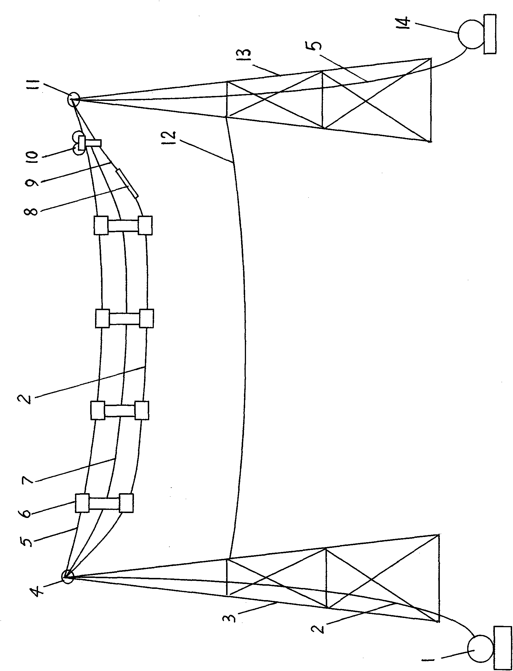
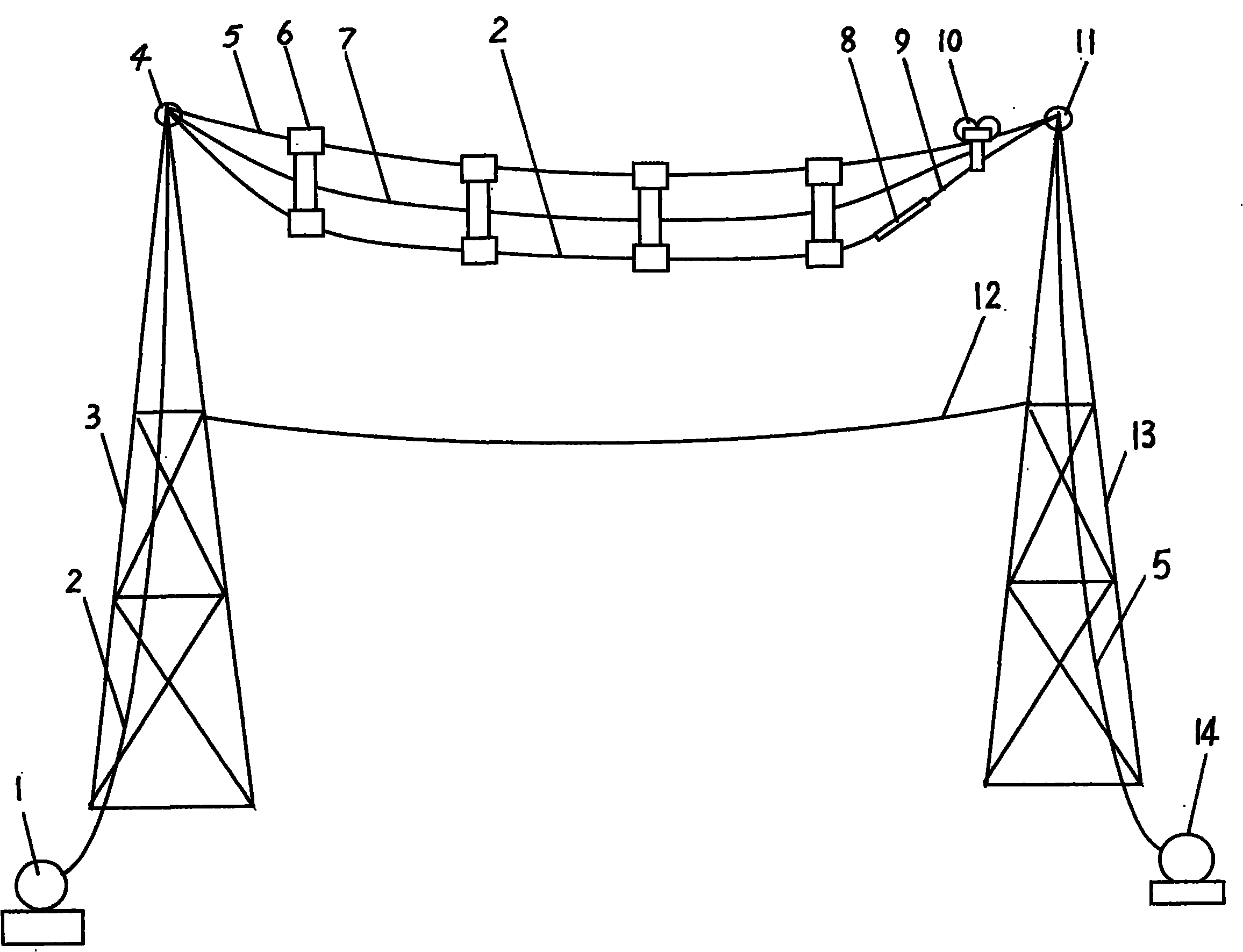
[0008] refer to figure 1 , on the old ground wire 5 between the iron tower 3 at one end and the iron tower 13 at the other end, a plurality of hanging pulleys 6 and a wire tractor 10 are hung, between the hanging pulley 6 and the iron tower 3 at one end, between adjacent hanging pulleys 6 Between the wire tractor 10 and the hanging pulley 6, all are fixedly connected with the connecting rope 7, and the interval length is 15 meters-20 meters. Pass through the hole at the bottom of each suspension pulley 6 after the top, and connect with the insulating rope 9 on the wire tractor 10 with a clamp 8, start the wire tractor 10 to pull the new ground wire 2 to the other end iron tower 13 , the wire tractor 10 reaches the top of the iron tower 13 at the other end, takes off the old ground wire 5 and installs it on the pulleys 4 and 11 of the iron towers at both ends, stretches the new ground wire 2 to a specified sag and connects it to the iron tower 3. On 13, fix the connecting rope...


PUM


Abstract

The invention provides a method for replacing an optical fiber composite overhead ground wire or a common overhead ground wire without power cut. The method comprises the following steps of: hanging a plurality of suspension pulleys and a wiring tractor on an old ground wire between two iron towers; connecting the suspension pulleys and an iron tower at one end, connecting every two adjacent suspension pulleys and connecting the wiring tractor and the suspension pulleys by a connection rope fixedly with an interval of between 15 and 20 meters; unwinding a new ground wire from a wire unwinding drum which is arranged on the ground, wherein after passing through the top of the iron tower at one end, the new ground wire passes through a hole on the lower part of each suspension pulley and is connected together with an insulating rope which is arranged on the wiring tractor by a clamp; starting the wiring tractor so as to draw the new ground wire to the iron tower at the other end; when the wiring tractor reaches the top of the iron tower at the other end, taking the old ground wire down and arranging the old ground wire on pulleys which are arranged on the iron towers at two ends; after stretching the new ground wire to specified sag, connecting the new ground wire and the iron tower and fixing the connection rope on the iron tower at the other end; loosening the old ground wire so as ensure that the positions of the old and new ground wires are exchanged; drawing the old ground wire back by a wire winding drum which is arranged on the ground, and demounting the connection rope, the insulating rope, the suspension pulleys and the wiring tractor at the same time; and precisely adjusting the sag of the new ground wire, arranging accessories, positioning and strengthening. By the method, sags of the new and old ground wires can be controlled conveniently to ensure that the new ground wire and the old ground wire do not contact a power line.

Description

technical field [0001] The invention relates to a method for replacing overhead ground wires of power transmission lines, in particular to a method for replacing optical fiber composite overhead ground wires or common overhead ground wires without power failure. Background technique [0002] In the existing method of replacing the optical fiber composite overhead ground wire or ordinary overhead ground wire of the transmission line, in the process of dismantling the old ground wire and erecting the new ground wire, because the ground wire is easy to touch the power line and cause damage to the construction personnel, it is necessary to cut off the power construction. In this way, it will not only increase the cumbersome approval procedures, but also affect the production and domestic electricity consumption of units and residents, which will bring great inconvenience. Contents of the invention [0003] In order to overcome the shortcomings of existing methods for replacin...

Claims


Application Information

Patent Timeline
IPC IPC(8): H02G1/02H02G7/22
Inventor 吴永成刘运锋沈钦葛守防
Owner FUJIKURA HENGTONG AERIAL CABLE SYST
Why Eureka
Try Eureka