Supercharge Your Innovation With Domain-Expert AI Agents!

Partial wall-flow filter and method

A wall-flow filter and filter technology, applied in chemical instruments and methods, separation methods, membrane filters, etc., can solve the problems of high back pressure of filters, fuel economy defects, etc.

Inactive Publication Date: 2011-05-04
CORNING INC
View PDF3 Cites 7 Cited by
  • Summary
  • Abstract
  • Description
  • Claims
  • Application Information

AI Technical Summary

Problems solved by technology

"Active" regeneration, on the other hand, comes with fuel economy drawbacks
Additionally, conventional filters can have relatively high back pressure

Method used


Image

  • Partial wall-flow filter and method
  • Partial wall-flow filter and method
  • Partial wall-flow filter and method

Examples


other Embodiment approach

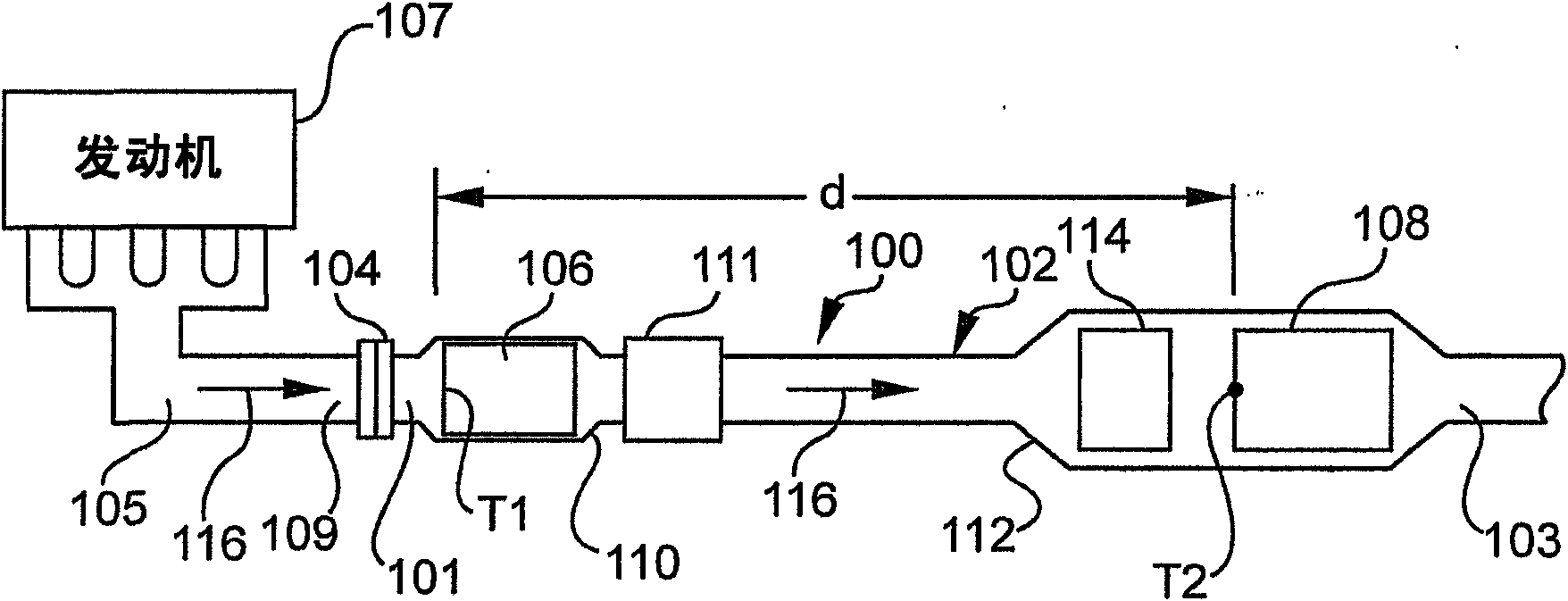
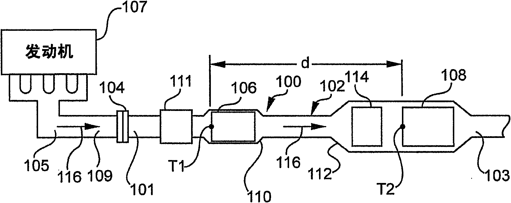
[0027] Other embodiments include partial wall flow filters having excellent properties for use in exhaust systems as described above. It should be understood that the partial wall flow filter may be used in an exhaust system as the only exhaust treatment component in the system. For example, the system may include only partial wall flow filters, which may or may not be catalyzed. Optionally, the partial wall flow filter can be used in conjunction with other conventional exhaust gas treatment components, and the partial wall flow filter is the only filter in the system. For example, the partial wall flow filter may be used in conjunction with a diesel oxidation catalyst (DOC) or NOx treatment assembly. For example, the partial wall flow filter may be preceded by an upstream DOC assembly. As discussed, catalysts may be used in the walls of partial wall flow filters, such as for treating carbon monoxide, hydrocarbons and / or nitrogen oxides, such as diesel oxidation catalysts or...


PUM


Abstract

A partial wall-flow filter having some unplugged flow-through channels and some plugged channels. Desirable combinations of filtration efficiency and back pressure may be provided by combinations of t wall <= 305 urn, MPD <= 20 [mu]m, %P >= 50 %, and CD >= 250 cpsi wherein t wall is the transverse thickness of the porous walls, MPD is a mean pore diameter of the porous walls, %P is the total porosity of the porous walls, and CD is the cell density of the channels. In one embodiment, some of the plugged channels are located adjacent to the inlet end and some are located adjacent to the outlet end. Systems and method including the partial wall-flow filter are also described.

Description

[0001] Cross References to Related Applications [0002] This application claims priority to US Provisional Application No. 61 / 057,079, filed May 29, 2008. field of invention [0003] This invention relates generally to wall flow filters for filtering exhaust gases, and more particularly to wall flow filters having some plugged channels and some unplugged channels. Background technique [0004] Diesel exhaust systems may include, for example, a diesel particulate filter (DPF) for removing particulates, such as soot, from diesel exhaust. The most widely used DPF is the wall flow filter. Conventional wall flow filters comprise a ceramic honeycomb body having longitudinal, generally parallel cell channels formed by a plurality of intersecting porous walls. The cells are typically plugged with a ceramic plugging cement to form a tessellated pattern of plugging at the ends of the honeycomb body. The cell cells of the filter typically have some unplugged ends at the inlet end o...

Claims


Application Information

Patent Timeline
IPC IPC(8): B01D46/24
CPCF01N3/0222F01N3/035B01D46/247B01D46/2429B01D46/2482B01D46/2455B01D46/24491B01D46/2459B01D46/2474B01D46/24492B01D46/2484B01D2279/30F01N3/021F01N3/2828F02B37/00F01N13/009Y02T10/12B01D46/2498
Inventor I·Z·阿迈德D·M·比尔A·K·海贝尔P·坦登
Owner CORNING INC
Features
  • R&D
  • Intellectual Property
  • Life Sciences
  • Materials
  • Tech Scout
  • Unparalleled Data Quality
  • Higher Quality Content
  • 60% Fewer Hallucinations
Learn More