Determination of the movement of a synchronous machine

A synchronous motor, synchronous motor technology, applied in motor control, electronic commutation motor control, elevator and other directions, to simplify the measurement layout, improve the parking accuracy, improve the accuracy of the effect

Active Publication Date: 2011-05-04
KONE CORP
View PDF8 Cites 6 Cited by
  • Summary
  • Abstract
  • Description
  • Claims
  • Application Information

AI Technical Summary

Problems solved by technology

[0009] The object of the present invention is to solve the problems presented above in the description of the prior art and the problems disclosed below in the description of the invention

Method used


Image

  • Determination of the movement of a synchronous machine
  • Determination of the movement of a synchronous machine
  • Determination of the movement of a synchronous machine

Examples


Embodiment Construction

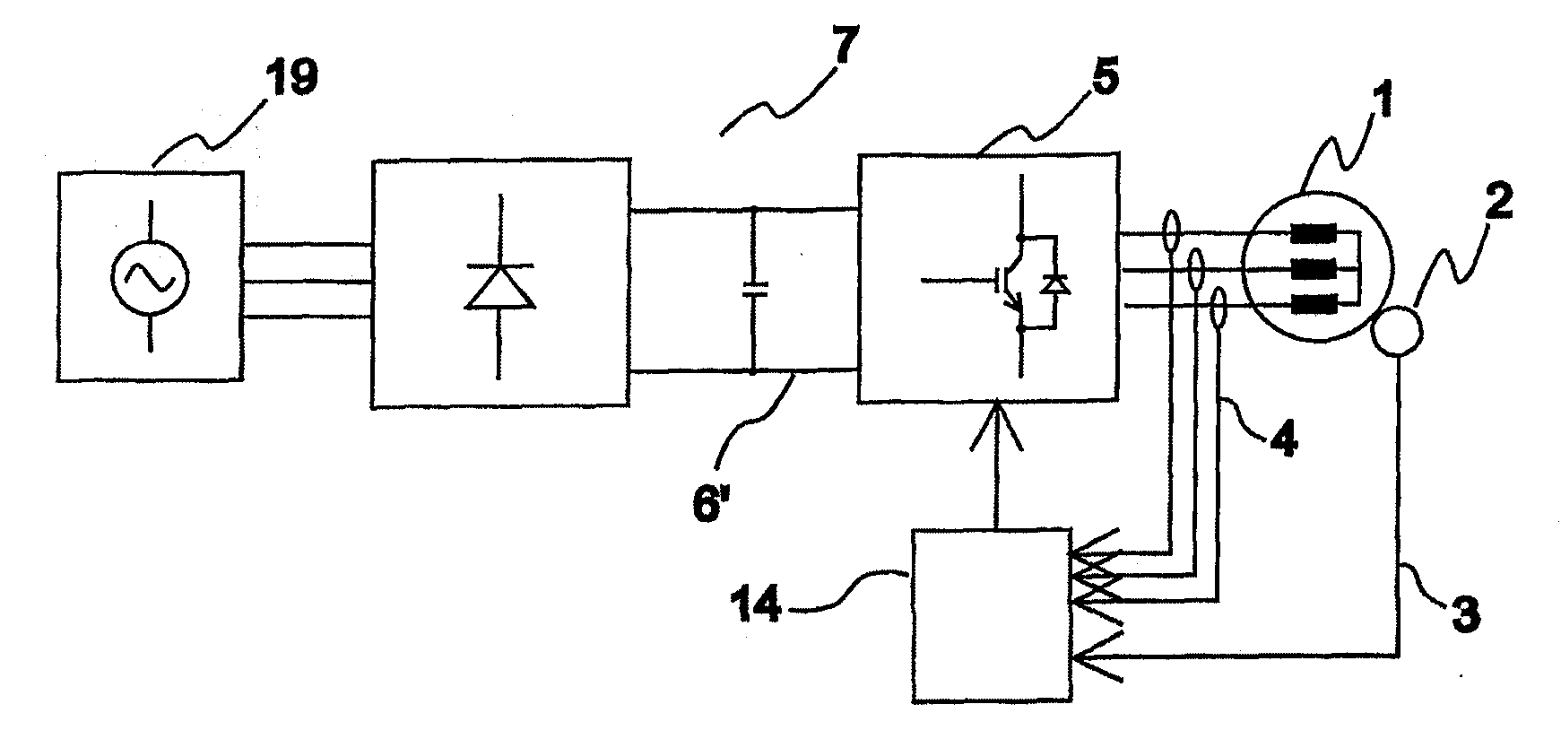
[0047] figure 1 A frequency converter 7 is shown, which comprises the device according to the invention for determining the movement of a synchronous machine. The frequency converter 7 is suitable for providing power between the synchronous machine 1 and the grid 19 . The frequency converter comprises a load bridge 5 connected to the stator windings of the synchronous machine. The control part 14 of the frequency converter is adapted to control the solid state switches of the load bridge 5 to form a variable amplitude and variable frequency control voltage to each phase of the stator winding of the synchronous machine. The encoder 2 is mounted to the outer rim of the rotor of the synchronous motor via a friction wheel, in which case, when the rotor rotates, the rotary shaft of the encoder fixed to the friction wheel also rotates via the friction wheel. The encoder comprises an output for a motion signal 3 representing the motion of the rotor of the synchronous machine.

[0...


PUM


Abstract

The invention relates to a method and an apparatus for determining the movement of a synchronous machine (1). The apparatus for determining the movement of a synchronous machine comprises a determination for at least one electrical magnitude (4,4') of the synchronous machine; a determination (9) of the position error of the rotor of the synchronous machine, which is fitted to determine the position error (8) of the rotor on the basis of the aforementioned at least one electrical magnitude (4) of the synchronous machine; and also a correction (10) of the movement signal of the incremental sensor, which is fitted to correct the read movement signal (3) of the incremental sensor on the basis of the aforementioned determination (9) of the position error of the rotor of the synchronous machine.

Description

technical field [0001] The object of the invention is a method for determining the motion of a synchronous motor as defined in the preamble of claim 1, a device for determining the motion of a synchronous motor as defined in the preamble of claim 4, and a method for determining the motion of a synchronous motor as defined in the preamble of claim 7. Apparatus for determining the movement of conveying means as defined in the preamble of . Background technique [0002] When adjusting the speed of a synchronous motor, it is common to use a measuring absolute encoder (such as a resolver) to identify the rotor position. Resolvers have extremely low measurement accuracy. Additionally, resolvers, as well as other absolute sensors, often must be mounted on the shaft of the motor because the construction of the motor can make it difficult to mount the sensor. Absolute sensors mounted on the shaft may also increase the axial length of the motor. [0003] More recently, different se...

Claims


Application Information

Patent Timeline
Patent Type & Authority Applications(China)
IPC IPC(8): H02P6/16B66B1/24
CPCB66B1/30H02P6/185H02P2203/01H02P2203/05B66B1/24H02P6/16
Inventor 劳里·斯托尔特图卡·考皮南
Owner KONE CORP
Why Eureka
Try Eureka