Shrink tunnel

A tunneling and heat shrinking technology, which is applied in the direction of wrapping paper shrinkage, packaging, wrapping paper, etc., can solve the problems of not getting jet flow, achieve the effect of optimizing mechanical properties and appearance properties, and minimizing energy costs

Inactive Publication Date: 2011-05-11
KRONES AG
View PDF11 Cites 23 Cited by
  • Summary
  • Abstract
  • Description
  • Claims
  • Application Information

AI Technical Summary

Problems solved by technology

The downside of this technique is that notable item ...

Method used


Image

  • Shrink tunnel
  • Shrink tunnel
  • Shrink tunnel

Examples


Embodiment Construction

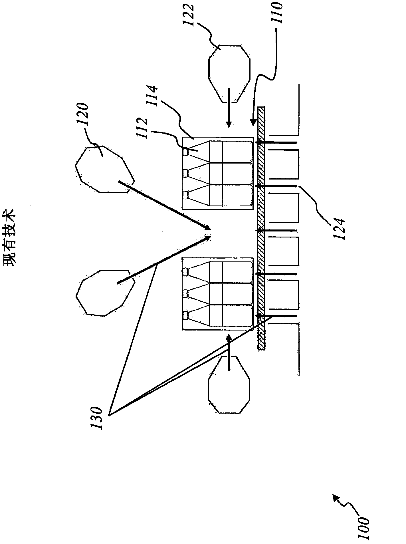
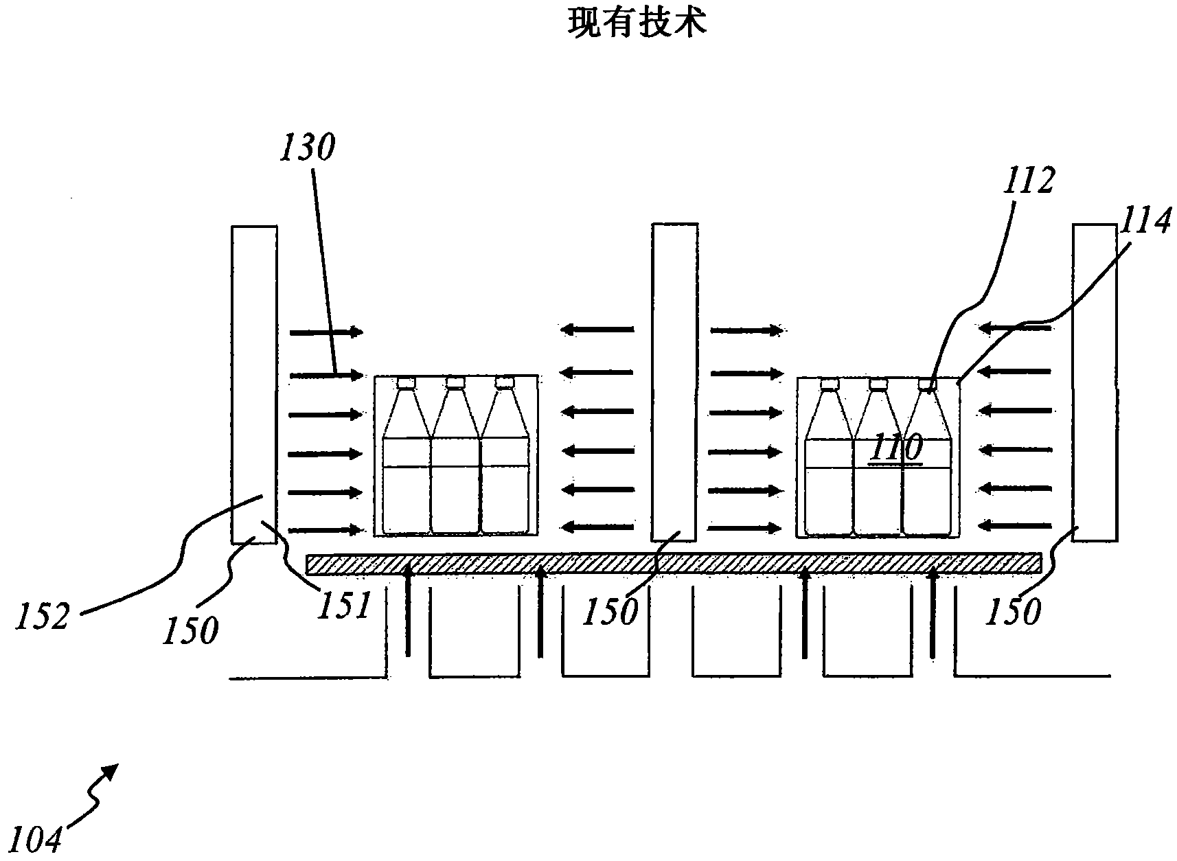
[0056] figure 1 and figure 2 It has been described in detail in the prior art.

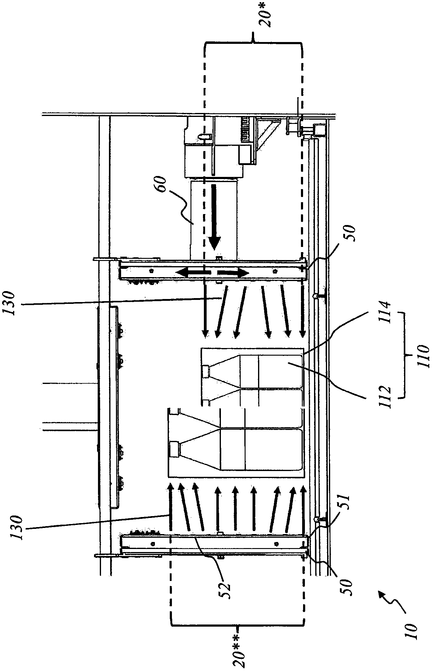
[0057] image 3 A schematic diagram of a constriction tunnel 10 according to the invention using ventilation shaft wall technology with variable air supply is shown. also, image 3 The relative adjustability of the nozzle rows with respect to each other is also shown.

[0058] The shrink tunnel 10 has at least one ventilation shaft 50 . The at least one ventilation shaft 50 is a hollow wall, for example made of metal, with at least one ventilation shaft wall 51 having nozzle openings 52 at least substantially over the entire length of the height of the constriction tunnel 10 . In general, the shrink tunnel 10 has two ventilation shafts 50 arranged parallel to one another and parallel and perpendicular to the goods transport section, wherein the ventilation shaft walls 51 are arranged in such a way that the nozzle openings 52 point towards the shrink tunnel 10 internal. Hot air or hot air 1...


PUM


Abstract

The invention provides a shrink tunnel (10) for the heat shrink of a film surrounding articles (112), which is preferably used for the heat shrink of a film of a container (110).The shrink tunnel comprises at least one transportation section for the articles (112), at least one ventilation shaft (50) and at least one mechanism (60) for conveying the airflow (130) to the ventilation shaft.The ventilation shaft is equipped with at least one shaft wall (51) equipped with a plurality of jet nozzles (52) directed to the articles.The airflow is introduced into the interior of the shrink tunnel through the jet nozzles.The shaft wall is equipped with an adjusting unit for adjusting the quantity or a flow angle (beta) of the airflow in the interior of the shrink tunnel.The invention is to provide a setting or adjustment of the hot-air nozzles in a shrink tunnel, which allows a simple and rapid adaptation to the articles to be packaged.

Description

technical field [0001] The invention relates to a shrink tunnel for thermally shrinking films according to the features of the preamble of claim 1 . Background technique [0002] Methods and devices are known from the prior art for packaging objects (packages) which use shrink films as wrapping wraps for objects. The shrink film is usually supplied as an endless material (endlos material) on a roll. [0003] The shrink film is divided inside the packaging device according to the size of the package. The film sheet is then wrapped around the item inside the device with the aid of a wrapping system. Next, the collection of items is transported through the shrink tunnel. Inside the shrink tunnel, warm air is supplied to the wrapped items, thereby tightening the shrink film so that it clings to the items and forms the finished package of shrunk items. [0004] In addition, shrink tunnels can be used to apply shrink labels to containers. In these processes, both the shrinkag...

Claims


Application Information

Patent Timeline
IPC IPC(8): B65B53/06
CPCB65B53/063B65B59/001
Inventor 克里斯蒂安·哈斯特雷特
Owner KRONES AG
Why Eureka
Try Eureka