

Direct drive engaging and disengaging device of washing machine
A technology of clutch device and washing machine, which is applied to washing devices, other washing machines, textiles and paper making, etc., can solve the problems of high cost, short service life, complex structure of electromagnetic clutch built into the motor, etc., and achieve weight reduction, efficiency improvement and stability Sex, increase the effect of concentricity and transfer efficiency
- Summary
- Abstract
- Description
- Claims
- Application Information
AI Technical Summary
Problems solved by technology
Method used
Image

Examples
Embodiment Construction
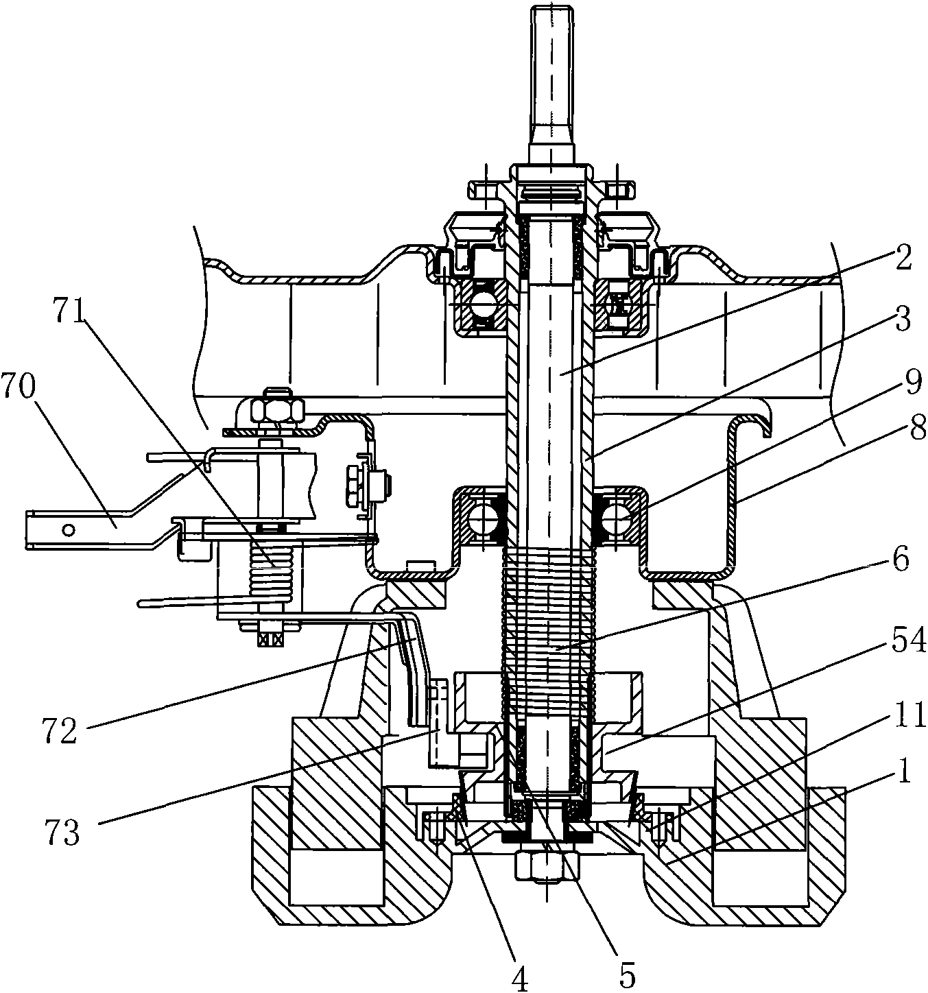
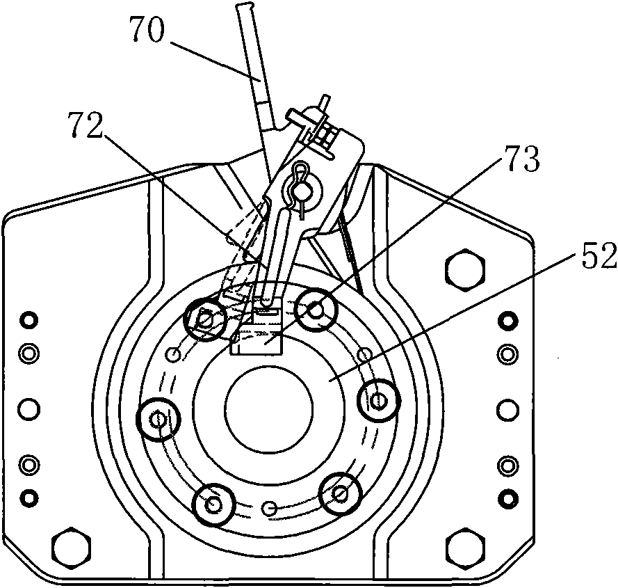
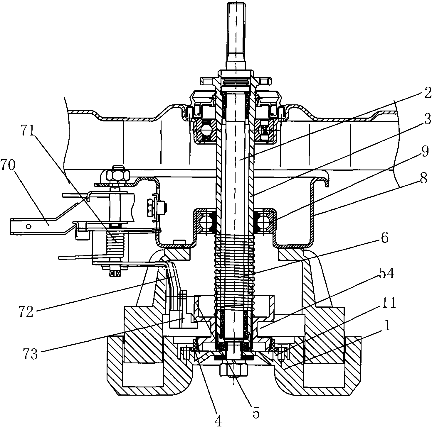
[0029] Such as Figure 1 to Figure 4 As shown, the direct drive clutch device of the washing machine according to the present invention includes a direct drive motor 1 installed at the bottom of the outer tub. The direct drive motor 1 directly transmits the pulsator shaft 2 that drives the pulsator, and is coaxially sleeved outside the pulsator shaft 2 to drive the dehydration bucket. The rotating dehydration shaft 3 is used to transmit the drive of the direct drive motor 1 to the pulsator shaft 2 alone or to the upper and lower split clutch structure of the pulsator shaft 2 and the dehydration shaft 3 at the same time. The clutch structure is tightly combined with the motor rotor 11 The clutch outer disk 4 that rotates together, the clutch inner sleeve 5 that is connected to the dehydration shaft 3 and can drive the dehydration shaft 3 to rotate together and slide axially on the dehydration shaft 3, and the clutch inner sleeve 5 that is set on the dehydration shaft 3 to provid...
PUM
 Abstract
Description
Claims
Application Information