Supercritical air energy storage system

一种超临界空气、储能系统的技术,应用在照明和加热设备、机器/发动机、液化等方向,能够解决压缩空气储能系统能量密度低等问题,达到提高土地和资源使用效率、能量密度高、环境友好的效果

Active Publication Date: 2011-05-11
INST OF ENGINEERING THERMOPHYSICS - CHINESE ACAD OF SCI
View PDF1 Cites 87 Cited by
  • Summary
  • Abstract
  • Description
  • Claims
  • Application Information

AI Technical Summary

Problems solved by technology

But at the same time, since no fossil fuel heat source is used, the energy density of the compressed air energy storage system is lower, which further highlights the dependence on large gas storage chambers.

Method used


Image

  • Supercritical air energy storage system
  • Supercritical air energy storage system
  • Supercritical air energy storage system

Examples


Embodiment

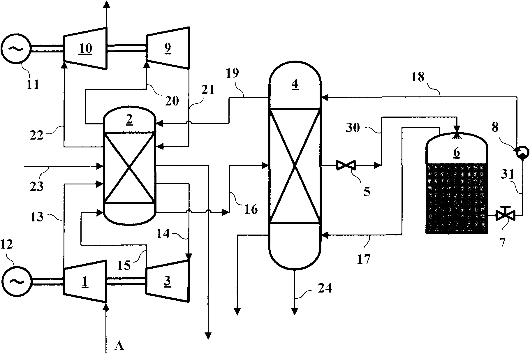
[0069] like figure 1 Shown is Embodiment 1 of the supercritical air energy storage system of the present invention. Among them, low-pressure compressor 1, heat storage / heat exchanger 2, high-pressure compressor 3, cold storage / heat exchanger 4, throttle valve 5, cryogenic storage tank 6, valve 7, cryopump 8, high-pressure expander 9, low-pressure Expander 10, generator 11, driving motor 12, pipelines 13, 14, 15, 16, 17, 18, 19, 20, 21, 122, 23, 24, 30, 31, air A.

[0070] The drive motor 12 is fixedly connected to the common transmission shafts of the compressors 1 and 3 , and the generator 11 is fixedly connected to the common transmission shafts of the expanders 9 and 10 . The low-pressure compressor 1 communicates with the heat storage / heat exchanger 2 through the pipeline 13 and the high-pressure compressor 3 through the pipelines 14 and 15 respectively. The inlet of low-pressure compressor 1 is connected with air A. The heat storage / heat exchanger 2 , the cold storage / ...


PUM


Abstract

The invention discloses a supercritical air energy storage system which is a novel energy storage system and relates to an energy storage technology. Air is compressed to a supercritical state (compression heat is stored simultaneously) by adopting off-peak (low-price) electricity of a power station, and the supercritical air is cooled, liquefied and stored (energy storage) by utilizing stored cold energy; during power consumption peaks, the liquid air is pressured to absorb heat to be in the supercritical state (the cold energy is recycled simultaneously), and after the compression heat is further absorbed, an expander drives a generator to generate power (energy release). The system provided by the invention has the advantages of high energy density, high efficiency, no limit by energy storage period and geographic conditions, suitability for various power stations (power stations of renewable energy sources including wind energy and the like), environment friendliness, low-and -medium temperature (heat value) waste heat recycle and the like.

Description

technical field [0001] The invention relates to the technical field of energy storage, in particular to an air energy storage system based on a supercritical process. Background technique [0002] For a long time, in order to meet the requirements of electric load, the power sector has to build power generation capacity according to the maximum load requirement. On the one hand, this has caused a large amount of surplus and waste of power generation capacity. On the other hand, the power sector has to often limit power consumption during peak hours of power consumption. Especially in recent years, the number of large units in my country's power grid has continued to increase, the power regulation capacity of the power system itself has been limited, and the peak-to-valley ratio of the system load has continued to increase, so there is an urgent need for economical, reliable and efficient power storage systems Match it. Especially for nuclear power plants and other power sys...

Claims


Application Information

Patent Timeline
Patent Type & Authority Applications(China)
IPC IPC(8): F03D9/02
CPCF25J3/04842F25J1/0012F25J1/0037F25J1/0045F25J1/0228F25J1/0251F25J3/04018F25J3/04054F25J3/04084F25J3/04187F25J3/04193F25J3/04309F25J3/044F25J3/04581F25J2205/24F25J2230/04F25J2230/08F25J2230/30F25J2240/10F25J2240/90F25J2245/90F01K7/22F01K5/02F03G7/06F25J2235/02Y02E60/16F01K3/004
Inventor 陈海生谭春青刘佳张冬阳徐玉杰
Owner INST OF ENGINEERING THERMOPHYSICS - CHINESE ACAD OF SCI
Why Eureka
Try Eureka