

Bistable solenoid valve and manufacturing method thereof
A solenoid valve and bistable technology, applied in the field of solenoid valves, can solve the problems of complicated control and coil heating, and achieve the effects of simple control, reduction of temperature rise, and reduction of power-on time.
- Summary
- Abstract
- Description
- Claims
- Application Information
AI Technical Summary
Problems solved by technology
Method used
Image

Examples
no. 2 approach
[0053] The second embodiment is a transformation made on the basis of the first embodiment, and the components having the same structure and function as those in the first embodiment will not be repeated one by one. Here is an explanation of the difference between the two:
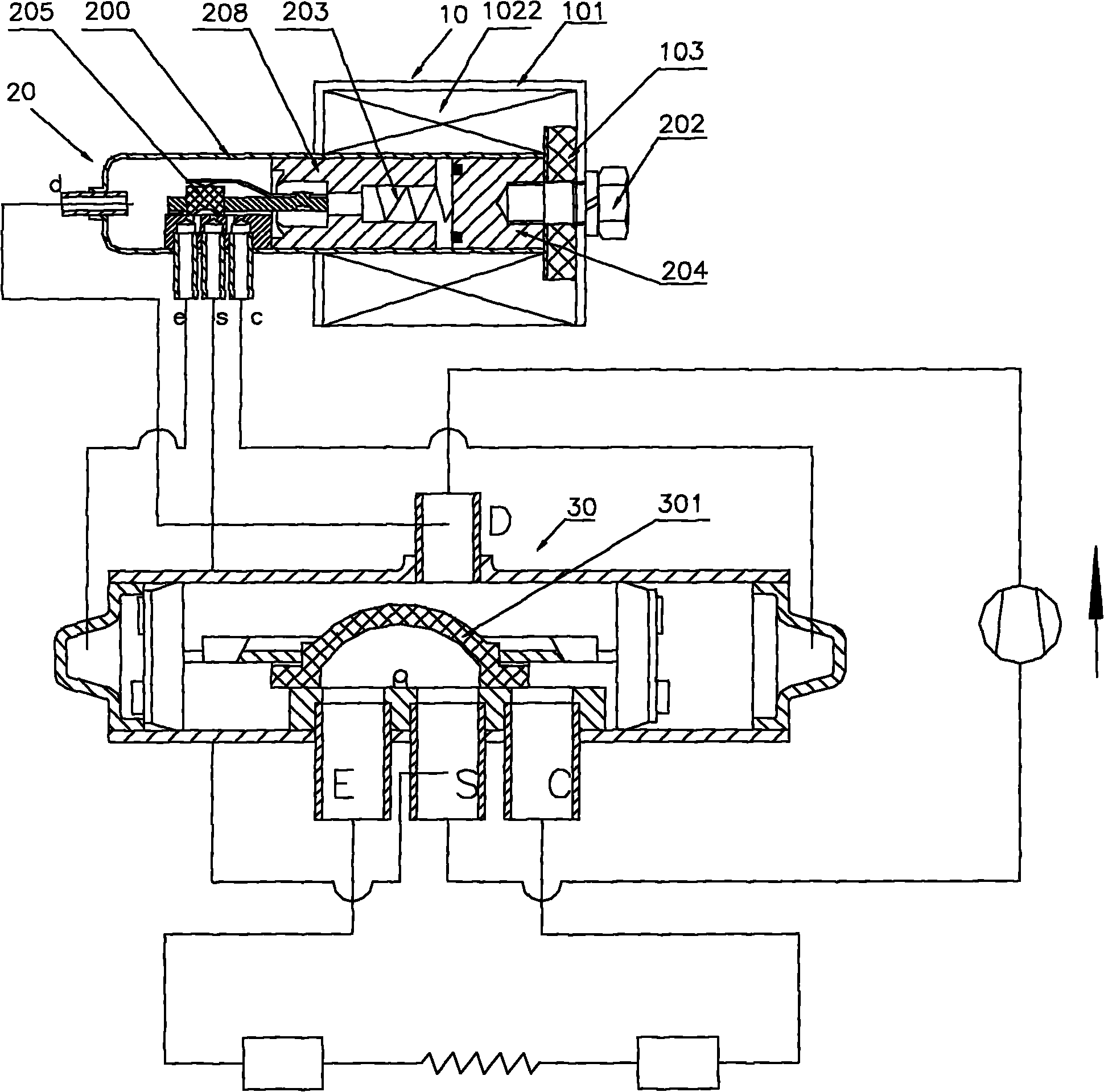
[0054] In the second embodiment, the inserts are respectively mounted on the insert grooves provided on the opposite flat surfaces of the flange portions 1022cb / 1022cc / 1022cd, and inserts 1022f1, 1022f2, and 1022f3 are respectively installed on the insert grooves. When winding the coil winding, the inner wire ends of the winding are respectively connected to the tabs 1022f1 and 1022f2, and then wound on the annular spaces 1022cf and 1022cg respectively, thus obtaining the first winding 1022a and the second winding 1022b respectively.
[0055] In this embodiment, since the inserting pieces are respectively arranged on the three collar-shaped parts one by one, they are drawn out through three lead wires resp...
Embodiment approach
[0057] In addition to adopting the positions of the tabs in the first embodiment and the second embodiment, various setting combinations can also be made, as long as the inner wire ends of the first winding and the second winding are respectively connected to the first tab and the second As for the insertion piece, the outer wire ends of the first winding and the second winding are respectively connected to the second insertion piece and the third insertion piece.
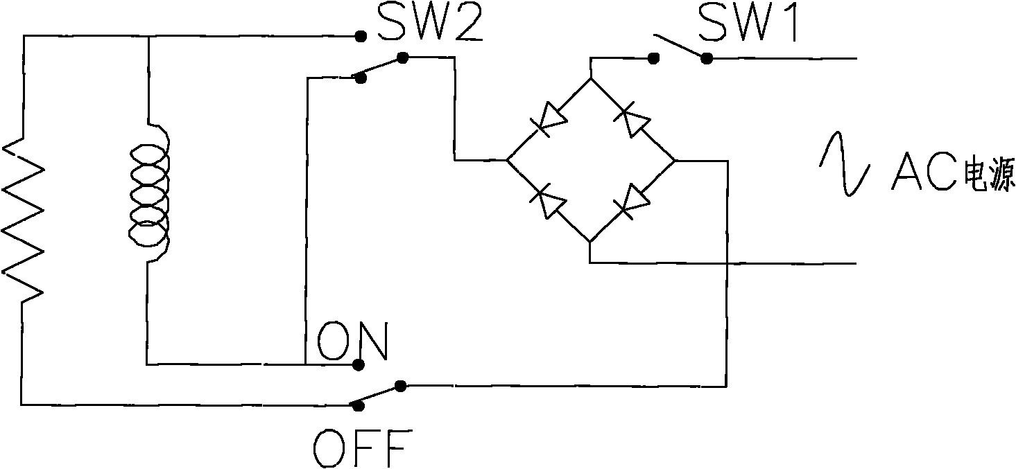
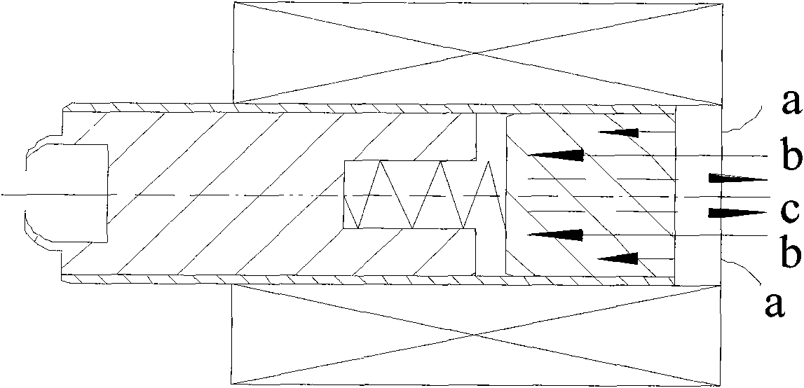
[0058] Combine below Figure 10 , Figure 11 , to illustrate the control method and working principle of the solenoid valve coil of the present invention. Figure 10 It is the electromagnetic coil control circuit diagram of the present invention, Figure 11 It is the working principle diagram of the electromagnetic coil of the present invention.
[0059] When the SW1 switch is turned on and the SW2 switch is turned ON, the first winding 1022a of the coil is fed with current, and the direction of the magnetic fie...
PUM
 Abstract
Description
Claims
Application Information