Method for determining sending time and receiving time of secondary pulses

A technology of receiving time and sub-pulse, applied in the direction of fault location, etc., can solve the problems of low success rate of testing high-resistance faults of power cables, the success rate of the second pulse test method cannot be guaranteed, and the fault waveform information cannot be accurately obtained. , to achieve the effect of avoiding blindness, reducing weight and improving success rate

Active Publication Date: 2011-05-11
SHANDONG KEHUI POWER AUTOMATION
View PDF0 Cites 7 Cited by
  • Summary
  • Abstract
  • Description
  • Claims
  • Application Information

AI Technical Summary

Problems solved by technology

Due to the great influence of the test conditions, the values ​​are scattered and not fixed, so the fault waveform information cannot be accurately obtained, and the success rate of testing high-resistance faults of power cables is not high
In order to improve the test success rate, an arc stabilizer is generally added to the low-voltage pulse coupling unit to prolong the arcing time by injecting more energy after the fault ignites the arc, but there is a big blindness in the preset secondary pulse sending time However, the success rate of the second pulse test method is still not guaranteed

Method used


Image

  • Method for determining sending time and receiving time of secondary pulses
  • Method for determining sending time and receiving time of secondary pulses
  • Method for determining sending time and receiving time of secondary pulses

Examples


Embodiment Construction

[0025] Under the binding Figure 1-4 The present invention will be described in detail.

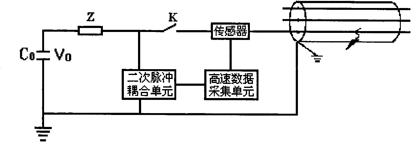
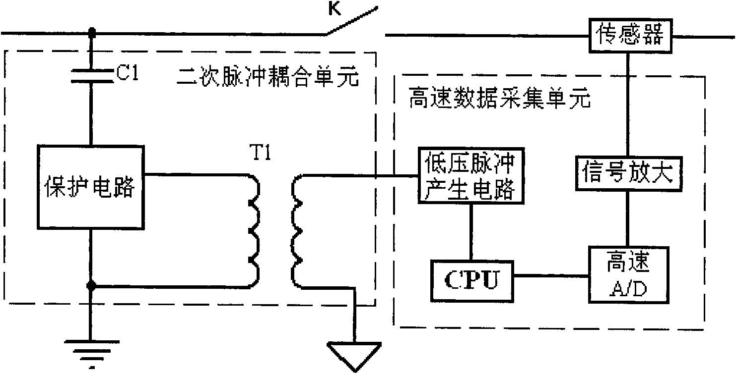
[0026] like figure 1 Shown: The signal transmitting circuit is discharged by the high-voltage signal generator capacitor C 0 , the series resistor Z in the high-voltage pulse discharge circuit, the discharge switch K, the sensor, the secondary pulse coupling unit and the high-speed data acquisition unit, a resistor Z is connected in series in the circuit, and the two ends of the resistor Z are respectively connected to the discharge capacitor C 0 It is connected with the discharge switch K, the discharge switch K is connected with the cable under test through the sensor through the wire, the output end of the sensor is connected with the signal amplification circuit, and the high-speed data acquisition unit is connected with the secondary pulse coupling unit.

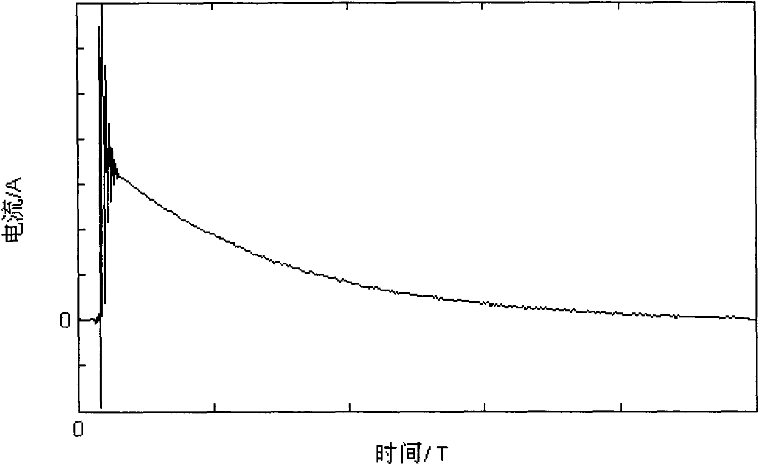
[0027] at t 0 time, the discharge switch K is closed, and the discharge capacitor C 0 The stored energy is released to the ca...


PUM


Abstract

The invention relates to a method for determining sending time and receiving time of secondary pulses, which belongs to the field of fault testing of cables, and is mainly used for testing of high resistance faults of the power cables. The method comprises the following steps: a) connecting a resistor Z in a high-voltage impulse-flash testing circuit in series, and respectively connecting two ends of the resistor Z with a discharge capacitor C and a discharge switch K; b) utilizing a sensor and a high-speed data acquisition unit for acquiring a discharge current signal i(t) generated by discharge of the discharge capacitor C; c) calculating instantaneous resistance at a cable fault point during the discharge period according to the discharge current signal i(t) and the circuit structure; d) selecting a period of special time corresponding to the instantaneous resistance during the t1-t2 period as a transmitting window; and e) sending and receiving secondary pulse signal waveform in the transmitting window. By applying the method, the blindness in setting sending time delay of the secondary pulses can be avoided, and the success ratio of testing of the secondary pulses can be significantly improved.

Description

technical field [0001] The invention relates to a method for determining the moment of sending and receiving a secondary pulse, which belongs to the field of cable fault testing. It is mainly used for testing high-resistance faults of power cables. Background technique [0002] The second pulse method is a test method for high-resistance faults of power cables. The principle of this method is to send low-voltage pulse signals to the cable under test twice successively. The primary signal contains cable fault point information, because the transmitted signal will show obvious differences in the fault point position, and the two received signal waveforms are compared, so that the distance to the fault point can be judged and calculated. [0003] One of the basic conditions for the application of the secondary pulse method is that the fault point of the cable has been punctured by high voltage when the secondary pulse is sent, and the arcing is stable and continuous. Depending...

Claims


Application Information

Patent Timeline
Patent Type & Authority Applications(China)
IPC IPC(8): G01R31/08
Inventor 李峰徐丙垠
Owner SHANDONG KEHUI POWER AUTOMATION
Why Eureka
Try Eureka