Method and device for designing three-dimensional closed guide blade with tubular type conical space

A space guide vane and tubular flow technology, applied in the field of hydraulic machinery, can solve the problems of flow performance influence, mutual interference of geometric shapes, difficult to control and ensure the flow performance of guide vanes, etc., and achieve good hydraulic performance and small flow loss. Effect

Inactive Publication Date: 2011-05-11
TSINGHUA UNIV
View PDF2 Cites 9 Cited by
  • Summary
  • Abstract
  • Description
  • Claims
  • Application Information

AI Technical Summary

Problems solved by technology

One is to first design a space curved airfoil with better hydraulic performance through the theory of equipotential flow, and then meet the tightness requirements by cutting the thickness and adjusting the curvature of the trailing edge. However, when changing the shape of the blade, it will Unpredictable effects on flow properties
The othe

Method used


Image

  • Method and device for designing three-dimensional closed guide blade with tubular type conical space
  • Method and device for designing three-dimensional closed guide blade with tubular type conical space
  • Method and device for designing three-dimensional closed guide blade with tubular type conical space

Examples


Embodiment 1

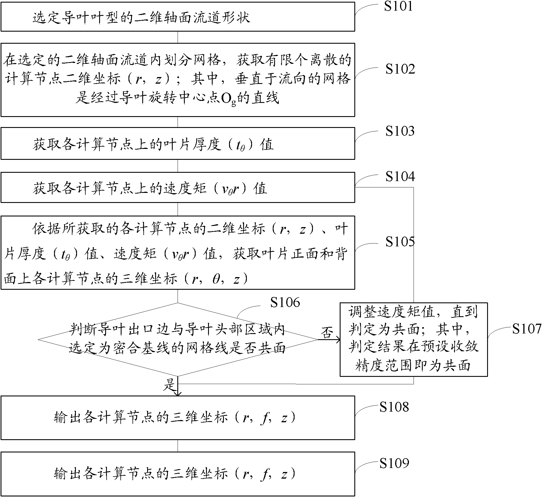
[0058] refer to figure 1 , which shows a flow chart of a three-dimensional close-fit design method for through-flow conical space guide vanes of the present invention, the method specifically includes:

[0059] Step S101, selecting the two-dimensional axial flow channel shape of the guide vane type;

[0060]Preferably, the two-dimensional axial flow channel shape of the selected guide vane type includes the following sub-steps:

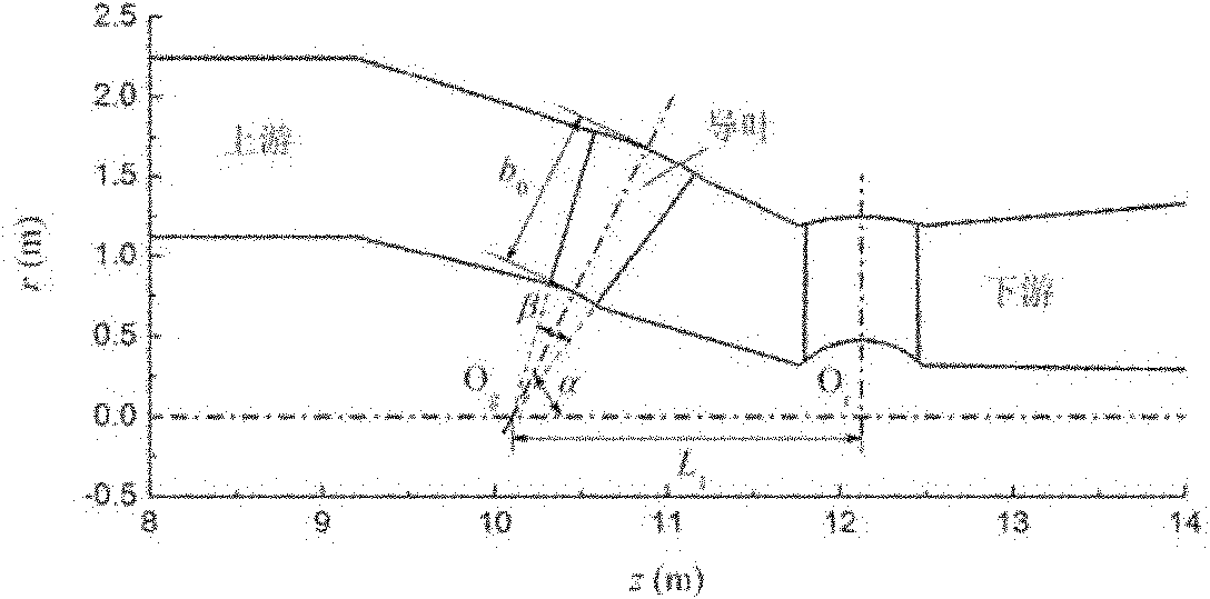
[0061] Determine the guide vane rotation center point O g ;

[0062] Determine the blade rotation center point O r ;

[0063] Determine guide vane height b 0 ;

[0064] Determine the inclination angle α between the rotation axis of the guide vane and the rotation axis of the runner;

[0065] Determine the axial angle β between the inlet side and the outlet side.

[0066] Preferably, the outlet side is selected to pass through the guide vane rotation center O g point line.

[0067] According to the hydraulic parameters and size of the unit, s...

Embodiment 2

[0133] refer to Figure 9 , which shows a structural diagram of a three-dimensional close-fit design device for through-flow conical space guide vanes of the present invention, the device specifically includes:

[0134] The first selection module 901 is used to select the shape of the two-dimensional axial flow channel of the guide vane type;

[0135] Preferably, the first selection module 901 specifically includes the following submodules:

[0136] The first determination sub-module 9011 is used to determine the rotation center point O of the guide vane g ;

[0137] The second determination sub-module 9012 is used to determine the blade rotation center point O r ;

[0138] The third determination sub-module 9013 is used to determine the guide vane height b 0 ;

[0139] The fourth determination sub-module 9014 is used to determine the inclination α between the rotation axis of the guide vane and the rotation axis of the runner;

[0140] The fifth determination sub-modul...


PUM


Abstract

The invention provides a method and device for designing a three-dimensional closed guide blade with a tubular type conical space. Through the invention, a spatial blade profile of the guide blade is designed by using a three-dimensional vortex surface method, which can ensure that the streaming loss of the blade is lesser and can supply all required circulation for acting of a rotating wheel. An optimization target is a closed plane by tightly sticking an exit of the guide blade with closing base lines. The velocity moment distribution control parameters are used as optimization variables and the blade capable of being closed is designed step by step by orderly changing the values of the optimization variables. The guide blade with a conical space designed by using the method provided by the invention has excellent waterpower performance, has enough precision to realize tightly closing and meets the flowing demand and structure demand at the same time.

Description

technical field [0001] The invention relates to the technical field of hydraulic machinery, in particular to a three-dimensional close-fit design method and device for through-flow conical space guide vanes. Background technique [0002] Tubular turbines have notable characteristics such as axial flow through, large flow capacity, high specific speed, good operating performance, and compact structure. They are widely used in large and medium-sized inland power stations and tidal power stations with low water heads below 25m. [0003] Most of the large tubular turbines adopt oblique water guide mechanism, and the movable guide vanes are distributed on the conical surface, which are called conical guide vanes. Since the tubular unit has no volute, the fixed guide vanes usually only play a supporting role without changing the circulation of the liquid flow, and the circulation required for the runner to do work is all provided by the movable guide vanes, so the performance of t...

Claims


Application Information

Patent Timeline
IPC IPC(8): G06F17/50
Inventor 樊红刚李凤超陈乃祥
Owner TSINGHUA UNIV
Why Eureka
Try Eureka