Band-pass filter

A band-pass filter and filter circuit technology, applied in the filter field, can solve the problems of band-pass filter filter performance reduction, large installation stress and welding stress, and lower quality factor, so as to reduce installation stress and welding stress and improve performance , Improve the effect of quality factor

Inactive Publication Date: 2011-05-11
HONG FU JIN PRECISION IND (SHENZHEN) CO LTD +1
View PDF1 Cites 3 Cited by
  • Summary
  • Abstract
  • Description
  • Claims
  • Application Information

AI Technical Summary

Problems solved by technology

However, in this kind of band-pass filter, the high-frequency signal is usually grounded directly through the capacitor or inductance device, the volume is still large, and the installation stress and welding stress are relatively large, which reduces the quality factor and reduces the filtering performance of the band-pass filter.

Method used


Image

  • Band-pass filter
  • Band-pass filter
  • Band-pass filter

Examples


Embodiment Construction

[0012] The present invention will be further described in detail below in conjunction with the accompanying drawings.

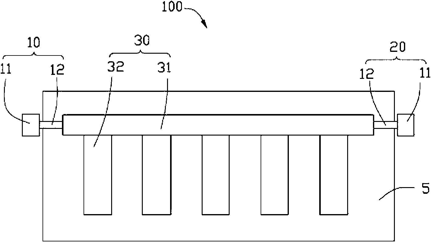
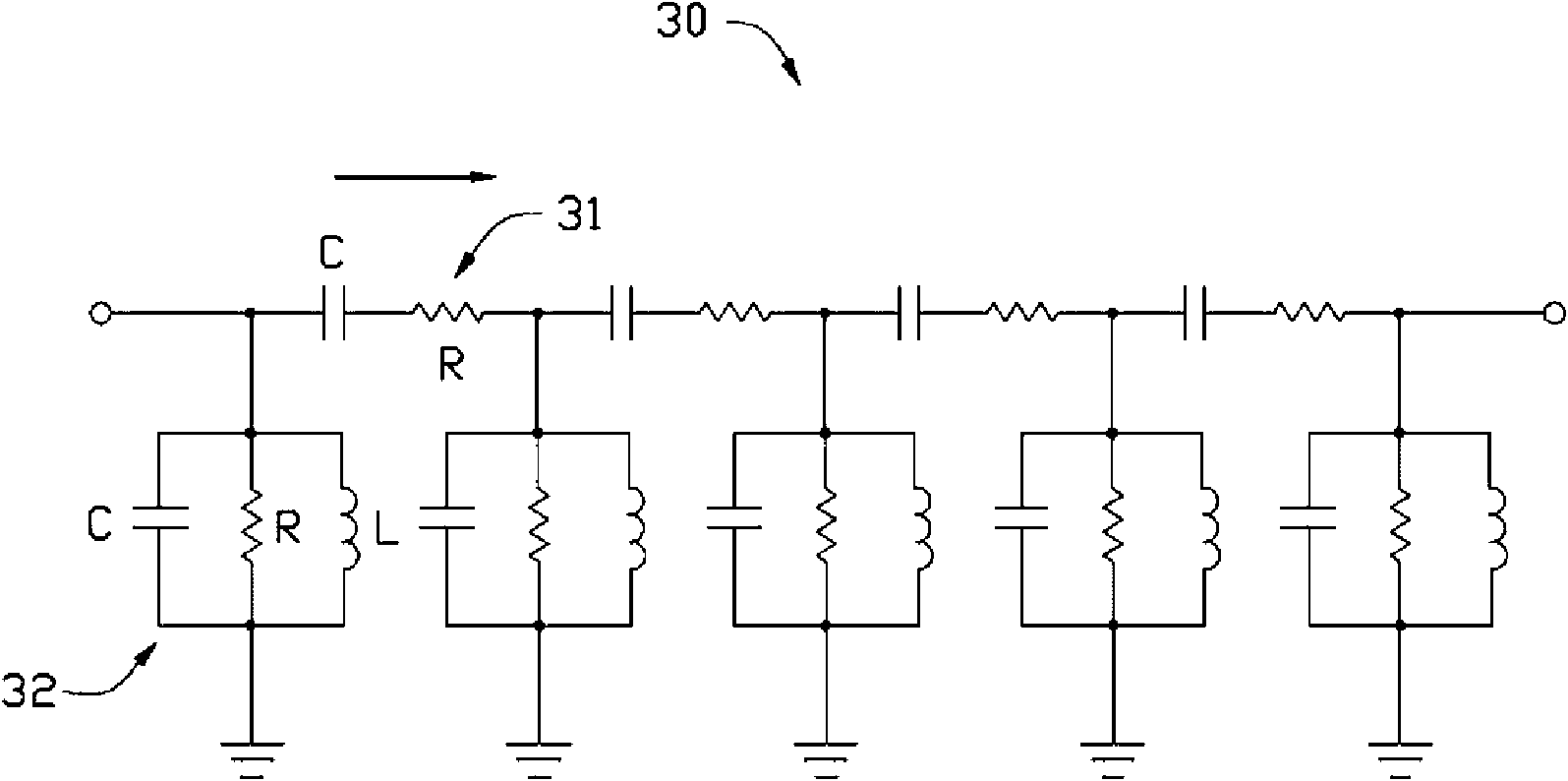
[0013] Such as figure 1 As shown, the bandpass filter 100 provided by the embodiment of the present invention includes an input terminal 10 , an output terminal 20 and a filter circuit 30 connecting the input terminal 10 and the output terminal 20 . In this embodiment, the bandpass filter 100 has a substrate 5, and the filter circuit 30 is formed on the substrate 5 by sputtering. It can be understood that the filter circuit 30 can also be etched or printed on a copper plate. formed on the substrate 5.

[0014] The input terminal 10 is used for inputting electromagnetic signals, and the output terminal 20 is used for outputting filtered electromagnetic signals to other connected devices (not shown). In this embodiment, the input end 10 and the output end 20 respectively include a microwave connector 11 , and each microwave connector 11 is connected to the fi...


PUM


Abstract

The invention provides a band-pass filter which comprises an input end, an output end and a filter circuit connecting the input end with the output end. The filter circuit comprises a main transmission line and a plurality of sections of short circuit transmission lines with the same impedance; and one end of each section of short circuit transmission line is connected in parallel to the main transmission line, and the other end is grounded. Both the main transmission line and the short circuit transmission lines adopt quarter-wavelength lossless transmission lines; and the phase difference of transmitting signals on the main transmission line and on the short circuit transmission lines is a half of pi. In the band-pass filter provided by the invention, a common electronic element is replaced by the short circuit transmission lines, so that the volume of the band-pass filter is reduced; and the quality factor of the short circuit transmission lines is higher than that of the common electronic element, so that the filter performance is improved.

Description

technical field [0001] The invention relates to a filter, in particular to a band-pass filter. Background technique [0002] A bandpass filter refers to a filter that can pass frequency components in a certain frequency range, but attenuate frequency components in other ranges to an extremely low level. An ideal bandpass filter should have a completely flat passband, ie no gain or attenuation within the passband, and all frequencies outside the passband are completely attenuated. [0003] Traditional band-pass filters are usually implemented by combining low-pass band-pass filters and high-pass band-pass filters, and because traditional band-pass filters usually use multiple electronic components, such as capacitors, inductors, resistors, etc. to form a filter circuit architecture , making the bandpass filter larger in size. Moreover, traditional electronic components are not effective in controlling insertion loss, return loss, and signal suppression outside the passband,...

Claims


Application Information

Patent Timeline
Patent Type & Authority Applications(China)
IPC IPC(8): H01P1/20H01P1/203
CPCH01P1/2039
Inventor 王文忠
Owner HONG FU JIN PRECISION IND (SHENZHEN) CO LTD
Why Eureka
Try Eureka