Dipole type antenna

An antenna and dipole technology, which is applied in the field of dipole antennas, can solve the problems of structure or shape design restrictions, dipole antenna 100 occupying the hardware space of wireless communication devices, etc., and achieve the effect of reducing hardware space and length

Inactive Publication Date: 2011-05-11
HTC CORP
View PDF2 Cites 1 Cited by
  • Summary
  • Abstract
  • Description
  • Claims
  • Application Information

AI Technical Summary

Problems solved by technology

[0003] However, it is worth noting that the length of the radiating arms 111 and 121 of the commonly used L-shaped radiators 110 and 120 is 1/4 of the guided wavelength, so t

Method used


Image

  • Dipole type antenna
  • Dipole type antenna
  • Dipole type antenna

Examples


Example Embodiment

[0030] In the following description, in order to present the consistency of the description of the present invention, in different embodiments, if there are elements with the same or similar functions and structures, the same element symbols and names will be used.

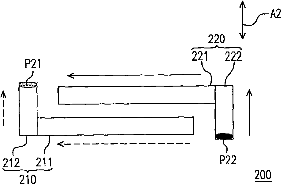
[0031] figure 2 Shown is a schematic structural diagram of a dipole antenna according to an embodiment of the present invention. refer to figure 2 , the dipole antenna 200 includes a first radiator 210 and a second radiator 220 . Wherein, the first radiator 210 includes a radiation arm 211 and an extension arm 212 , and the second radiator 220 includes a radiation arm 221 and an extension arm 222 .

[0032] In physical configuration, as far as the first radiator 210 is concerned, the first end of the radiation arm 211 is electrically connected to the extension arm 212 , and the second end of the radiation arm 211 is opposite to the extension arm 222 of the second radiator 220 . On the other hand, as far as th...


PUM


Abstract

The invention provides a dipole type antenna which comprises a first radiating body and a second radiating body, wherein the first radiating body comprises a first radiating arm and a first extending arm, and the second radiating body comprises a second radiating arm and a second extending arm. During entity configuration, the first extending arm and the second extending arm are not mutually adjacent, and the first radiating arm and the second radiating arm are mutually parallel.

Description

technical field [0001] The present invention relates to an antenna, and in particular to a dipole antenna. Background technique [0002] The antenna is one of the indispensable components of the wireless communication device, which is related to the communication quality and applicable range of the wireless communication device. Among them, a dipole antenna is a widely used antenna. figure 1 It is a schematic diagram of the structure of a traditional dipole antenna. refer to figure 1 , the dipole antenna 100 is mainly composed of two symmetrical L-shaped radiators 110 and 120 . In physical configuration, the extension arms 112 and 122 of the L-shaped radiators 110 and 120 are adjacent to each other, and the radiation arms 111 and 121 of the L-shaped radiators 110 and 120 extend on both sides of the extension arms 112 and 122 . By this, if figure 1 From the current direction of the antenna marked by arrows at a certain moment, the two currents flowing through the radiati...

Claims


Application Information

Patent Timeline
IPC IPC(8): H01Q9/04
Inventor 黄奂衢卢仁宸
Owner HTC CORP
Why Eureka
Try Eureka