Excitation source for superconducting magnet and its operating method
A technology of superconducting magnet and excitation power supply, which is applied in the usage of superconducting elements, electrical components, emergency protection circuit devices, etc., can solve the problem of cutting off danger and achieve the effect of preventing damage
- Summary
- Abstract
- Description
- Claims
- Application Information
AI Technical Summary
Problems solved by technology
Method used
Image
Examples
no. 1 Embodiment approach
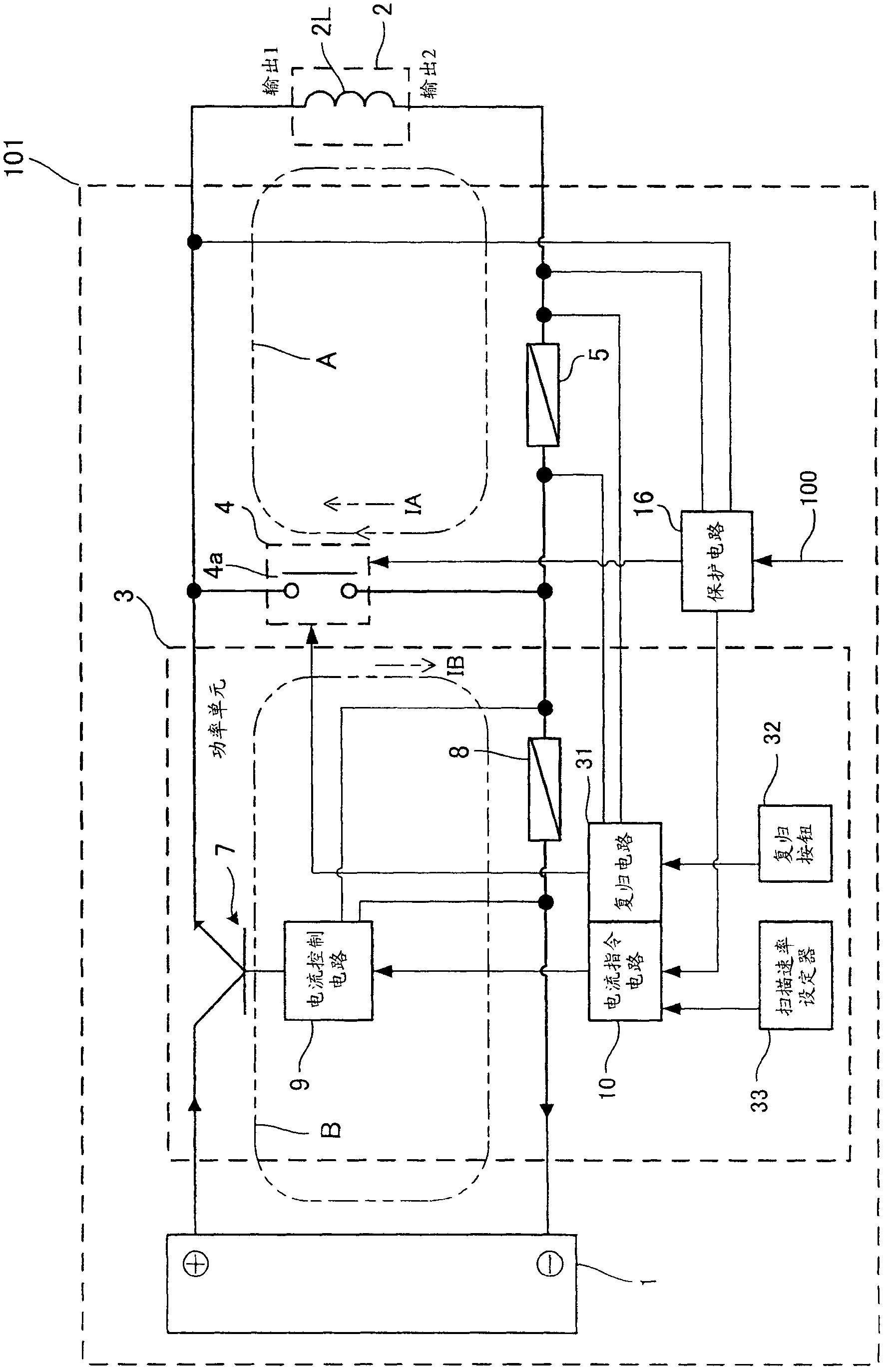
[0056] figure 1 It is a configuration diagram showing the field power supply 101 according to the first embodiment of the present invention.
[0057] (Structure of the excitation power supply 101)
[0058] The excitation power source 101 is connected to the superconducting coil 2L, and is a power source for exciting the superconducting magnet 2 including the superconducting coil 2L. The superconducting coil 2L is wound from a superconducting wire.
[0059] Such as figure 1 As shown, the excitation power supply 101 includes a power supply 1, a power unit 3, a first shunt resistor (first current detector) and a protection circuit 16 (protection device).
[0060] (power supply)
[0061] The power source 1 includes a transformer (not shown) connected to an AC power source, a transistor circuit (not shown) for supplying a smooth DC current rectified by the AC power of the transformer to the superconducting coil 2L, and the like. In addition, a commercially available switching ...
no. 2 Embodiment approach
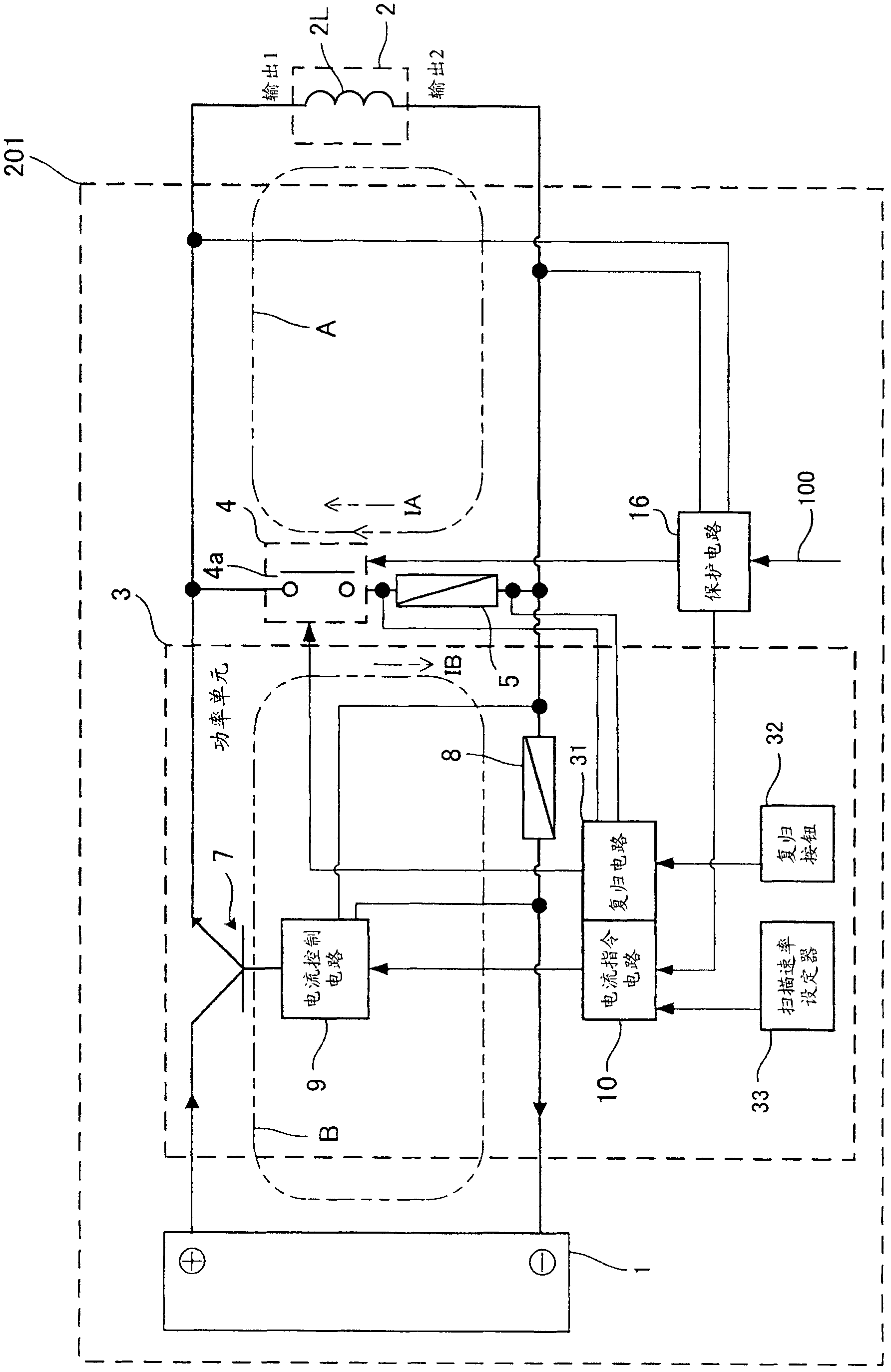
[0091] image 3 It is a configuration diagram showing the field power supply 201 according to the second embodiment of the present invention. The only difference from the first embodiment lies in the position of the first shunt resistor (first current detector). In the present embodiment, the first shunt resistor 5 is provided in parallel with the superconducting coil 2L. In this way, the first shunt resistor 5 may be provided at a position where the current IA passing through the superconducting coil 2L after the contact 4a of the protective relay is closed can be detected. In other words, the first shunt resistor 5 is arranged in series with the contact 4a, and is arranged between the output circuit B of the power unit 3 and the circuit A on the side of the superconducting coil 2L when the contact 4a is closed. public part.
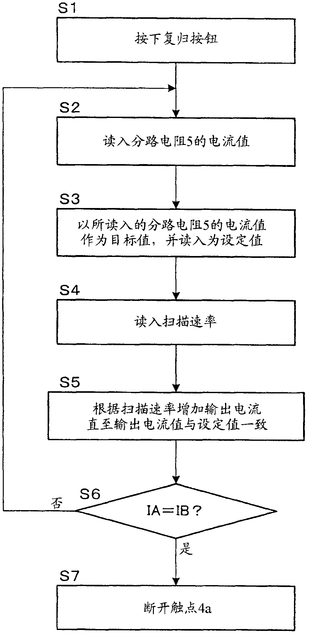
[0092] In this embodiment, the current control circuit 9 increases the output current value of the power unit 3 at a predetermined scan rate, so tha...
no. 3 Embodiment approach
[0100] Figure 4 It is a configuration diagram showing the field power supply 301 according to the third embodiment of the present invention. This embodiment differs from the first embodiment mainly in that the field power supply 301 of this embodiment includes two (multiple) power units. In addition, the field power supply may include three or more power units.
[0101] Such as Figure 4 As shown, the excitation power supply 301 includes a power supply 1, a first power unit 13, a second power unit 23, a first shunt resistor 5 (first current detector), a main control circuit 12 (main control device), a distributor 14 ( command distribution device), scan rate setter 33, protection circuit 16 (protection device), reset button 32 and reset circuit 131.
[0102] (1st current detector)
[0103] The first shunt resistor 5 is a current detector that detects the output current value of the entire excitation power supply 301 . In addition, the first current detector is installed t...
PUM
 Abstract
Description
Claims
Application Information
 - R&D
- Intellectual Property
- Life Sciences
- Materials
- Tech Scout
- Unparalleled Data Quality
- Higher Quality Content
- 60% Fewer Hallucinations
Browse by: Latest US Patents, China's latest patents, Technical Efficacy Thesaurus, Application Domain, Technology Topic, Popular Technical Reports.
© 2025 PatSnap. All rights reserved.Legal|Privacy policy|Modern Slavery Act Transparency Statement|Sitemap|About US| Contact US: help@patsnap.com


