Distributed illumination node control system and control method thereof

A lighting node and control system technology, applied in energy-saving control technology, lighting devices, lamp circuit layout, etc., can solve problems such as wasting electric energy, achieve great flexibility, avoid financial budget pressure, and increase construction costs

Active Publication Date: 2015-05-06
黄富杰 +2
View PDF3 Cites 0 Cited by
  • Summary
  • Abstract
  • Description
  • Claims
  • Application Information

AI Technical Summary

Problems solved by technology

However, this scheme also has the disadvantage of wasting electric energy

Method used


Image

  • Distributed illumination node control system and control method thereof
  • Distributed illumination node control system and control method thereof
  • Distributed illumination node control system and control method thereof

Examples


Embodiment Construction

[0048] The present invention will be further described in detail below in conjunction with the accompanying drawings.

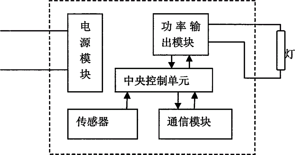
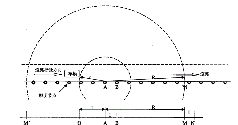
[0049] Such as figure 1 As shown, the present invention discloses a distributed lighting node control system, which includes a plurality of lighting nodes, each lighting node includes a light source and a power supply module that provides electric energy for it, and also includes a sensor, a communication module, and a power output module And the central control unit; the sensor is used to detect the vehicle signal within the range r, and send the inspection result to the central control unit, the central control unit is used to control the working status of the power output module and the light source, and the communication module is used to send or receive the range The broadcast information in R, the communication module receives the broadcast information and transmits it to the central control unit to control the working status of the power output module ...


PUM


Abstract

A road lighting device, a corresponding distributed node energy-saving lighting system and a method for operating the same. The road lighting device is connected to a light source (111) and has a power module (112). The road lighting device further comprises a sensing control unit and a communication control unit, wherein the sensing control unit enables the light source to be in a normal lighting state according to a vehicle signal, and the communication control unit enables the light source to be in a normal lighting state according to broadcast information containing a triggering instruction code. The sensing control unit and the communication control unit can separately or jointly control the light source, thus achieving intelligent control, rendering it possible for each road lamp equipped with such a road lighting device to independently carry out intelligent judgment on road usage and carry out dynamic energy-saving adjustment in real time, so as to ensure necessary useful illuminance and eliminate useless illuminance as far as possible. By using the distributed node energy-saving lighting system and the method for operating the same, all the road lamps are interconnected to form a network, thereby achieving intelligent automatic identification of failure and information feedback, as well as remote intelligent management and point-to-point control.

Description

technical field [0001] The invention belongs to the technical field of electric power control equipment, and relates to a distributed lighting node control system and a control method thereof. Background technique [0002] In order to achieve energy-saving effect, the existing lighting node control system usually adopts the following control types: [0003] The first one is through timing control. This kind of scheme requires controlling the illumination of street lamps at different time periods. When the road is in a relatively busy traffic period, the street lamps are adjusted to be in a normal working state, and when it is in the middle of the night, due to the scarcity of road vehicles, in order to achieve For the purpose of energy saving, the illumination of street lamps is reduced to half. This scheme is to automatically control the street lamps by timing. Although it can achieve a certain energy saving effect, when there are no vehicles on the road, this scheme also h...

Claims


Application Information

Patent Timeline
Patent Type & Authority Patents(China)
IPC IPC(8): H05B37/02H05B39/04H05B41/36
CPCH05B47/11H05B47/115H05B47/22Y02B20/40
Inventor 黄富杰温携勇江志清
Owner 黄富杰
Why Eureka
Try Eureka