Optical fiber cable and optical fiber tape

一种光纤缆线、光纤带的技术,应用在光纤带以及光纤缆线领域,能够解决光纤大形变及光损失等问题,达到经济性优良、取出性优良、充分长期可靠性的效果

Active Publication Date: 2011-05-11
NIPPON TELEGRAPH & TELEPHONE CORP
View PDF8 Cites 39 Cited by
  • Summary
  • Abstract
  • Description
  • Claims
  • Application Information

AI Technical Summary

Problems solved by technology

However, the conventional optical fiber ribbon has bending anisotropy such that it is difficult to bend in the width direction due to its shape, and if it is bent in the width direction in the optical fiber cable, large deformation and optical loss will occur in the optical fiber, so It is necessary to adopt a fiber optic ribbon and cable structure that can suppress this

Method used


Image

  • Optical fiber cable and optical fiber tape
  • Optical fiber cable and optical fiber tape
  • Optical fiber cable and optical fiber tape

Examples


no. 1 Embodiment approach

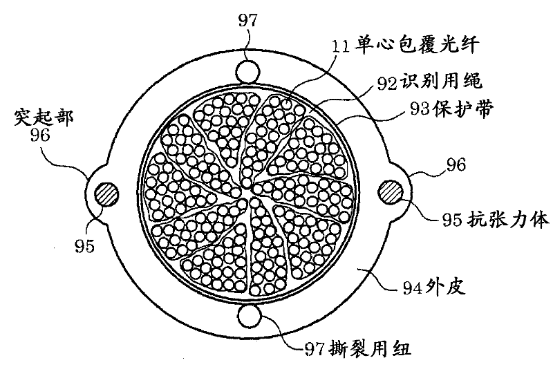
[0062] figure 1 It is a cross-sectional view showing an optical fiber cable according to an embodiment of the present invention. in figure 1 Among them, 11 is a single-core coated optical fiber, 92 is an identification cord, 93 is a protective tape, 94 is a sheath, 95 is a tension member, 96 is a protrusion, and 97 is a tear button.

[0063] Such as figure 1 As shown, a unit is formed by winding the identification cord 92 on the outer circumference of an optical fiber bundle obtained by gathering a plurality of, for example, 20 single-core coated optical fibers 11 with a diameter of 0.25 mm denser than straight. A plurality of, for example, 10 of the units are twisted in one direction to form a densely packed outer periphery, and a rolled layer composed of a plurality of thinner protective tapes 93 is provided, and an outer skin 94 is added to the outer periphery to form a density Very high 200-core multi-core fiber optic cable. The unit is configured using an optical fiber ribb...

Embodiment approach 2

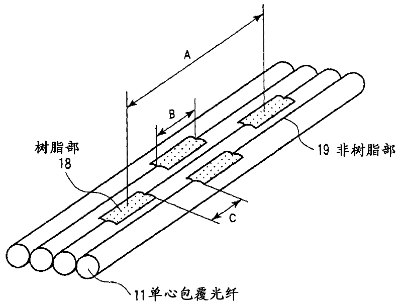
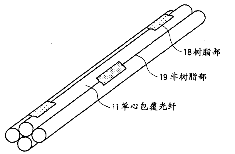
[0112] Hereinafter, embodiments of the present invention will be described in detail with reference to the drawings. Figure 8 (a) is a cross-sectional view showing an example of the optical fiber ribbon of the first embodiment of the present invention, Figure 8 (b) is a cross-sectional view showing another example of the optical fiber ribbon of the first embodiment of the present invention. in Figure 8 In (a), 11, 12, 13, 14 are single-core coated optical fibers, and 15, 16, 17 are connecting portions.

[0113] Such as Figure 8 As shown in (a), a plurality of (n) such as n=4 single-core coated optical fibers 11, 12, 13, and 14 with an outer diameter d (μm) are arranged, and each single-core coated optical fiber 11, 12, 13, and 14 are arranged so as to be separated from each other without touching each other, and the adjacent single-core coated optical fibers 11, 12, 13, 14 are continuously connected in the longitudinal direction through n-1, that is, three connecting portions ...

Embodiment approach 3

[0157] figure 1 , Figure 13 The optical fiber cable described in the above further includes a lateral pressure protection layer made of a metal tube 99 on the outer periphery of the outer sheath 94. The metal pipe 99 can be provided as a corrugated pipe that has been corrugated. Figure 15 Is explained in figure 1 The optical fiber cable described in is a diagram showing a case where a metal tube 99 is provided. Figure 16 Is explained in Figure 13 The optical fiber cable described in is a diagram showing a case where a metal tube 99 is provided. in Figure 15 , Figure 16 In the optical fiber cable, since the metal tube 99 serves as a protection against the cable side pressure, it does not need to be laid in the pipeline and can be directly buried underground.


PUM


Abstract

Provided is a single-core coated optical fiber (11) having such a curve loss characteristic that an optical loss increase at a bending radius 13 mm is 0.2 dB / 10 turn or below. An optical fiber tape conductor includes two-dimensionally arranged resin portions (18) for bonding each two adjacent single-core coated optical fibers (11). The resin portions (18) are arranged apart from one another in the longitudinal direction of the optical fiber tape conductor. An optical fiber cable includes a cable core unit for containing a plurality of sets of the single-core coated optical fibers (11) constituting the optical fiber tape conductor which are twisted together.

Description

Technical field [0001] The present invention relates to optical fiber ribbons and optical fiber cables that are components of information wiring using optical fibers outdoors and indoors. Background technique [0002] Currently, with the increase in broadband services, the number of FTTH subscribers using optical fiber has increased dramatically. As a result, in basic equipment such as pipelines for laying optical fiber cables, the space for additional laying of optical fiber cables continues to be insufficient. Therefore, making the diameter of the optical fiber cable smaller and increasing the density is very effective for the effective use of infrastructure equipment. [0003] As an optical fiber cable with a reduced diameter and an increased density, for example, Patent Document 1 discloses an optical fiber in which the increase in light loss with respect to bending is reduced, and an optical fiber with a combination of multiple pairs of the outer periphery of the optical fibe...

Claims


Application Information

Patent Timeline
Patent Type & Authority Applications(China)
IPC IPC(8): G02B6/44
CPCG02B6/4403G02B6/441G02B6/4433
Inventor 户毛邦弘山田裕介保苅和男
Owner NIPPON TELEGRAPH & TELEPHONE CORP
Why Eureka
Try Eureka