Emptying cartridge, method for emptying chamfers filled with rod-shaped objects and device for bringing together mass flows, in particular for an emptying cartridge

A product and material flow technology, which is applied in the field of at least two vertical and rod-shaped product collection areas that control the product material flow in the emptying box, achieves the effects of simple structure, easy implementation and improved functional reliability.

Active Publication Date: 2011-05-18
KOERBER TECH GMBH
View PDF11 Cites 10 Cited by
  • Summary
  • Abstract
  • Description
  • Claims
  • Application Information

AI Technical Summary

Problems solved by technology

In other words, the known device is not adapted to reliably

Method used


Image

  • Emptying cartridge, method for emptying chamfers filled with rod-shaped objects and device for bringing together mass flows, in particular for an emptying cartridge
  • Emptying cartridge, method for emptying chamfers filled with rod-shaped objects and device for bringing together mass flows, in particular for an emptying cartridge
  • Emptying cartridge, method for emptying chamfers filled with rod-shaped objects and device for bringing together mass flows, in particular for an emptying cartridge

Examples


Embodiment Construction

[0020] The emptying box shown in the picture is used to empty containers on the hopper station filled with rod-shaped products, but it can also be used as a stand-alone unit.

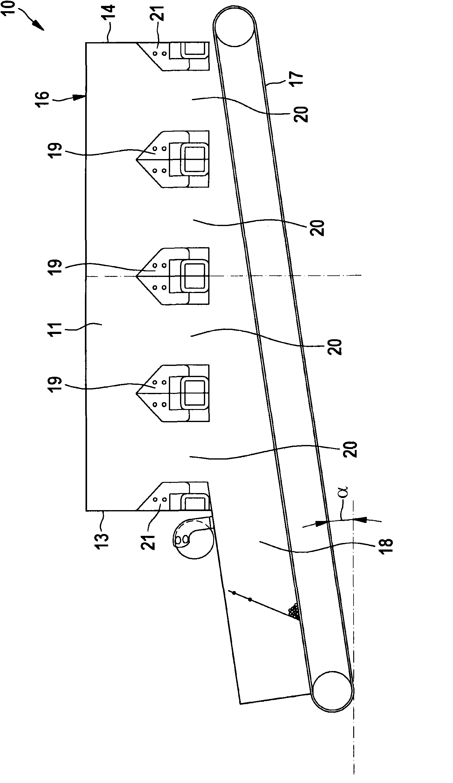
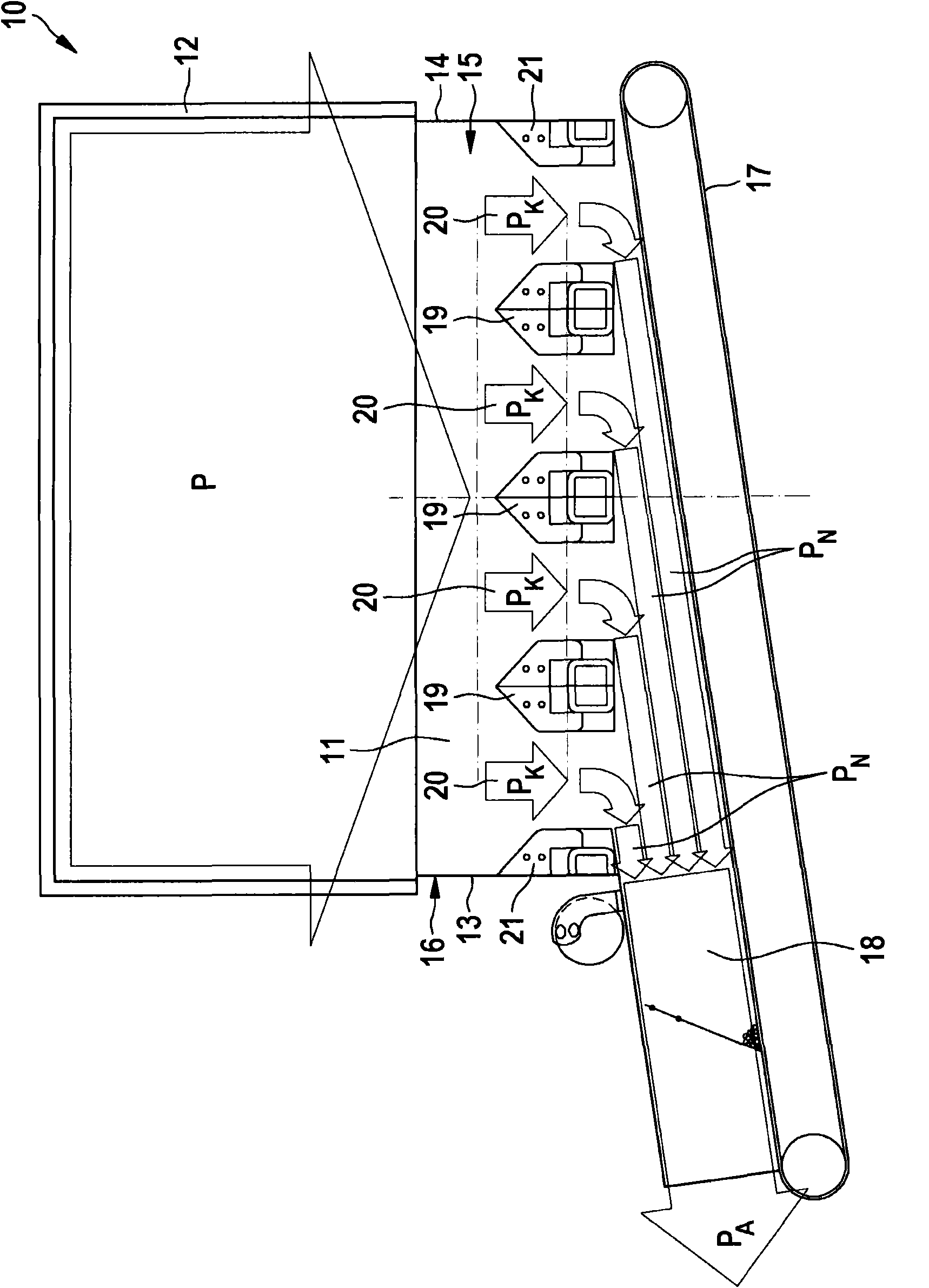
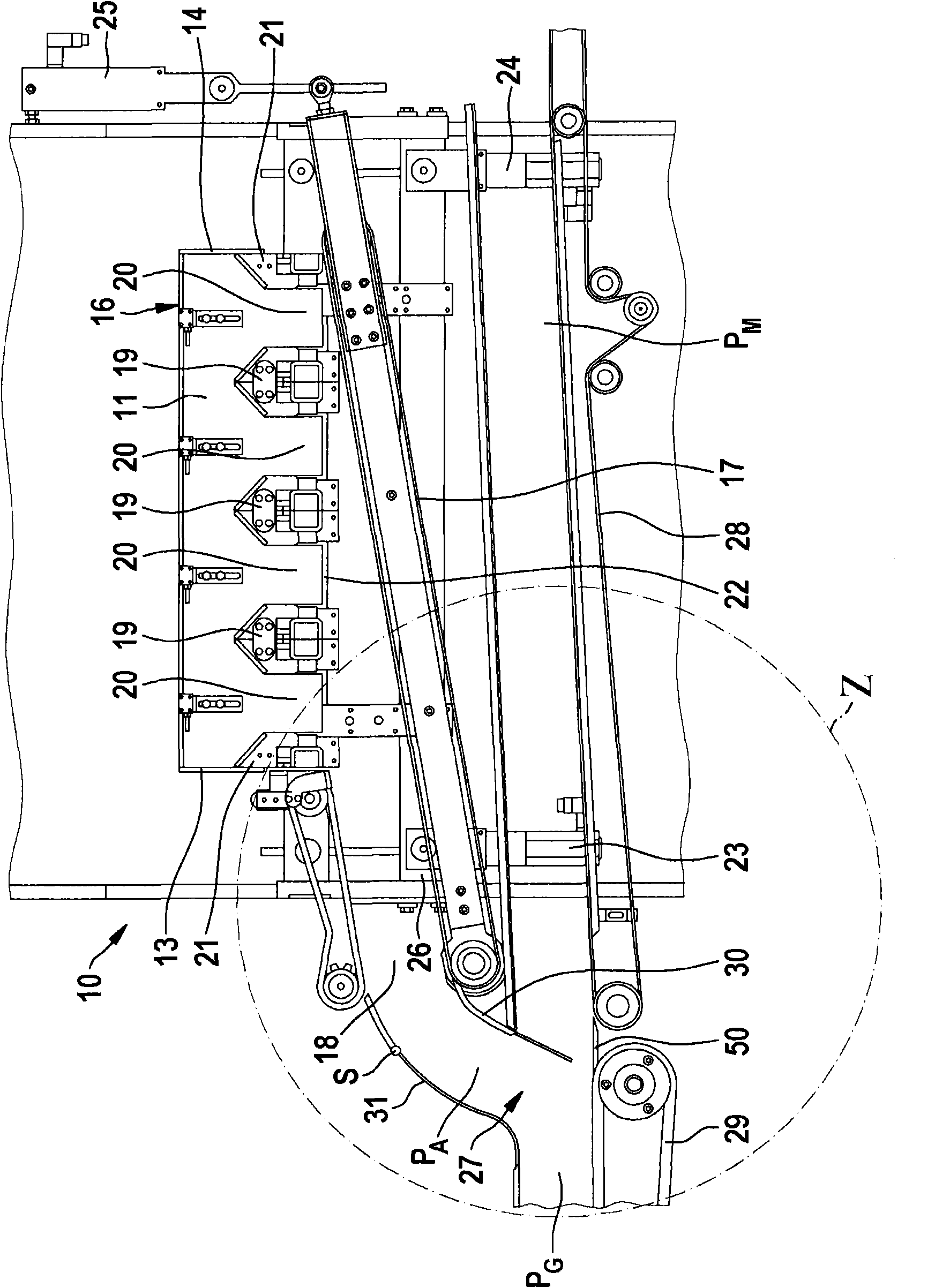
[0021] The first embodiment of the emptying box 10 comprises a collection area 11 for flowing product from a container 12, such as a hopper or trough hopper. The collection area 11 is bounded on all sides. This means that the collection area 11 is bounded by two side walls 13 , 14 , a front wall 15 (omitted from the figures for greater clarity) and a rear wall 16 . In the upward direction of the container 12 , the collection area is designed to be open, but can optionally be closed with a suitable closure element. The collection area 11 is bounded downwards by a transfer element 17 . The conveying element 17 is spaced apart from the collection area 11, so that the conveying element 17 forms a channel 18 in which the product is conveyed. Inside the collection zone 11 at least one flow control element ...


PUM


Abstract

The invention relates to an emptying cartridge, a method for emptying chamfers filled with rod-shaped objects and a device for bringing together mass flows, in particular for an emptying cartridge. The emptying cartridge comprises: a receiving space (11) for receiving the rod-shaped objects from the chamfer, wherein the receiving space is opened upwards along the chamfer direction and limited downwards by a conveying element (17) for conveying the products and formed by one canal (18); at least one flow controlling element (19, 21), wherein the distance between each flow controlling element and the conveying element is adjustable, characterized in that: the conveying element (17) for forming the canal and for conveying the products is arranged in an inclined way and according to the product diameter, the distance between the inclined angle Alpha and the conveying element (17) and each flow controlling element (19,21) is adjusted when keeping the product figure by the adjustability of each flow controlling element (19,21) and/or conveying element (17).

Description

technical field [0001] The invention relates to an emptying box of a hopper emptying station for emptying a hopper filled with rod-shaped products, in particular a trough-shaped hopper, comprising a collection area for rod-shaped products coming from the hopper, the collection The zone is open upwards in the direction of the hopper and is bounded downwards by a conveying element forming a channel for transporting the product and comprising at least one in the collecting zone for forming at least two controlled emptying boxes for the product The material flow control element of the vertical guide channel of the material flow, wherein the distance between each material flow control element and the conveying element can be adjusted. The invention also relates to a method for emptying a hopper, in particular a trough hopper, filled with rod-shaped product, comprising the steps of: opening the hopper or trough hopper; directing the flow of product through the emptying box The coll...

Claims


Application Information

Patent Timeline
IPC IPC(8): A24C5/356A24C5/35A24C5/34B65G11/20B65G47/19B65B19/04G01B21/10
CPCA24C5/35
Inventor T·彼得斯A·奥斯特林P·布德尼M·霍恩T·米勒M·纳比A·迈耶
Owner KOERBER TECH GMBH
Why Eureka
Try Eureka