Method and tooling for installing camshafts

An installation method and camshaft technology, applied in metal processing, manufacturing tools, metal processing equipment, etc., to achieve the effect of convenient and fast assembly process and reasonable method steps

Active Publication Date: 2015-06-10
CHERY AUTOMOBILE CO LTD
View PDF6 Cites 0 Cited by
  • Summary
  • Abstract
  • Description
  • Claims
  • Application Information

AI Technical Summary

Problems solved by technology

[0003] The purpose of the present invention is to provide a camshaft installation method to solve the problem of fixing the camshaft and the frame by means of tooling when the camshaft and the frame need to be fixed separately

Method used


Image

  • Method and tooling for installing camshafts
  • Method and tooling for installing camshafts
  • Method and tooling for installing camshafts

Examples


Embodiment 1

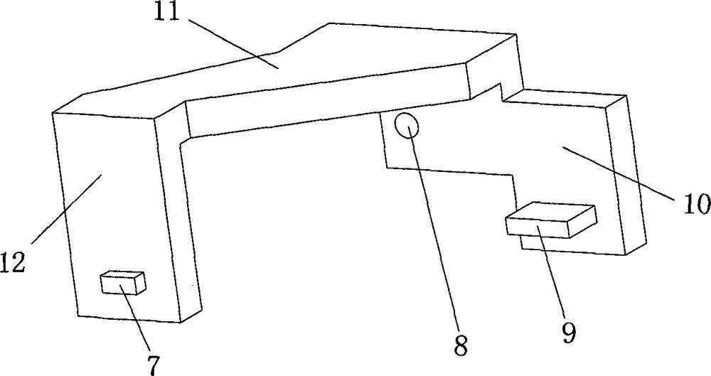
[0021] Example 1, such as figure 1 As shown, a camshaft installation tool can be divided into three parts as a whole, which includes a front arm 12, a rear arm 10, and a connecting arm 11. The front arm 12 is provided with a first protruding key 7 that matches the groove on the rear end of the exhaust camshaft 2; the rear arm 10 is provided with a groove that matches the rear end of the intake camshaft 3 The second protruding key 9 and the bolt holes 8 for fixing the installation tool on the frame 1 are provided.

Embodiment 2

[0022] Embodiment 2, a camshaft installation tool, in order to adapt to the frame 1, the connecting arm 11 is adapted to the upper top surface of the frame, and the rear arm 10 is adapted to the rear end surface of the frame 1 . All the other are with embodiment 1.

Embodiment 3

[0023] Embodiment 3, a camshaft installation tool, the shape of the first protruding key 7 and the second protruding key 9 is a cuboid. The forearm 12 and the rear arm 10 are parallel to each other. All the other are with embodiment 1 or 2.

[0024] In order to make its manufacturing process simple and low in cost, the tooling material is steel plate.

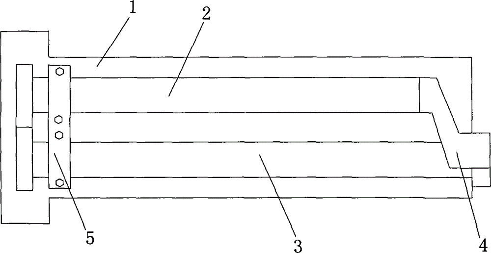
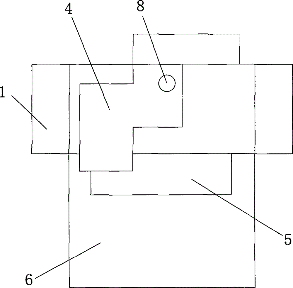
[0025] The exhaust camshaft and the intake camshaft are fixed through the cylinder head, the camshaft frame and a separate camshaft bearing cap. During the assembly process, the camshaft installation tool 4 needs to be used to sub-assemble the camshaft, and then the camshaft The shaft fits correctly on the cylinder head.

[0026] In the present invention, the using method of camshaft installation tool comprises the following steps:

[0027] First, put the camshaft frame 1 upside down on the workbench, place the cleaned intake camshaft and exhaust camshaft on the camshaft frame, and turn the intake camshaft and exhaust camsha...


PUM


Abstract

The invention discloses a tooling for installing camshafts, comprising a front arm, a rear arm and a connection arm, wherein the rear arm is provided with a bolt hole used for fixing the tooling on a framework, the front arm is provided with a first protruding key adaptive to a groove arranged on an air exhaust camshaft, the rear arm is provided with a second protruding key adaptive to a groove arranged on an air inlet camshaft, the front arm and the rear arm are parallel to each other, and when the camshafts are required to be separately assembled and fixed, the camshaft installing tooling can be used for carrying out separated assembly to satisfy the requirements of an assembling process on convenience and rapidness. The tooling has the advantages of simple structure, low cost and convenience in use.

Description

technical field [0001] The invention relates to the technical field of engine camshaft installation, in particular to a camshaft installation method and an installation tool. Background technique [0002] The camshaft is an important part of the engine, and the correct installation of the camshaft is directly related to the performance of the engine valve train. The current general practice is to place the camshaft directly on the cylinder head first, and then fix the camshaft frame on the cylinder head by bolts to complete the installation and fixation of the camshaft. This general installation method is only applicable to the case where the camshaft is directly fixed through the cylinder head and the frame. Due to the structural design and layout requirements, when the camshaft and the frame need to be sub-assembled, the general installation method cannot meet this requirement. So it is necessary to invent a separate tooling to fix the camshaft and assist the assembly of ...

Claims


Application Information

Patent Timeline
Patent Type & Authority Patents(China)
IPC IPC(8): B23P19/04
Inventor 赵鸿飞兰州余伟
Owner CHERY AUTOMOBILE CO LTD
Why Eureka
Try Eureka