Cargo pump apparatus for liquid cargo ship

A pump device and cargo technology, which is applied to cargo handling equipment, bulk cargo, ship hulls, etc., can solve the problems of increased personnel costs and equipment costs, excess equipment, etc., and achieve the effect of reducing operating costs and easy maintenance.

Inactive Publication Date: 2010-01-20
SHIN KURUSHIMA DOCKYARD CO LTD
View PDF9 Cites 0 Cited by
  • Summary
  • Abstract
  • Description
  • Claims
  • Application Information

AI Technical Summary

Problems solved by technology

[0009] However, in a liquid cargo ship that is divided into 12 to 16 cabins, more than ten kinds of cargoes will not be packaged, and at most about 6 to 8 kinds of packages will be required, so it will not be on the starboard side divided by the central bulkhead. And the pair of holds on the port side contain different types of cargo, so if they are equipped with submersible pumps, not only will there be excess equipment, but also it will be necessary to control each pump, resulting in labor costs and equipment costs including maintenance. fee increase etc.

Method used


Image

  • Cargo pump apparatus for liquid cargo ship
  • Cargo pump apparatus for liquid cargo ship
  • Cargo pump apparatus for liquid cargo ship

Examples


Embodiment 1

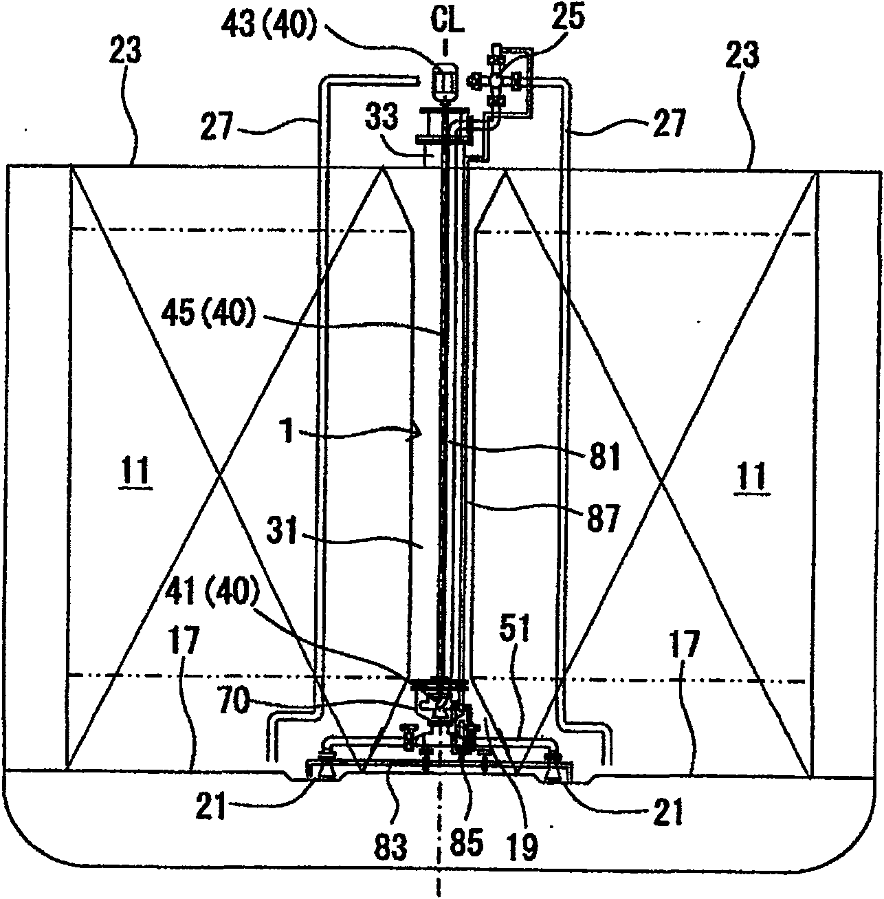
[0069] First, based on figure 1 as well as figure 2 The outline of the cargo pump device and the attached residual oil recovery device according to Embodiment 1 will be described, and then based on image 3 as well as Figure 4 The cargo pump device according to the first embodiment will be described.

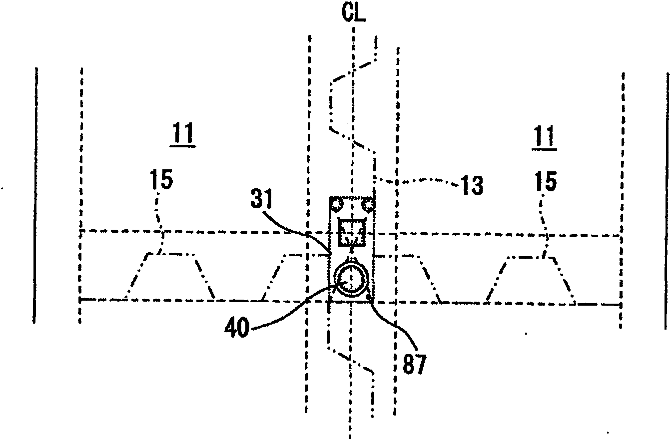
[0070] exist figure 2 In the figure, the upper part of the drawing is the bow side, and the lower part of the drawing is the stern side, such as figure 2 As shown, the cabin 11 is formed by liquid-tight partitioning by a central bulkhead 13 erected along the centerline (CL) of the cargo ship and a plurality of transverse bulkheads 15 vertically erected to the central bulkhead 13 . Moreover, the central partition wall 13 and the transverse partition wall 15 are arranged on the bottom vertical support pier 19 and the lower part of the transverse support pier (pedestal) which are approximately isosceles trapezoidal in cross-section, and the central partition wall 13 and th...

Embodiment 2

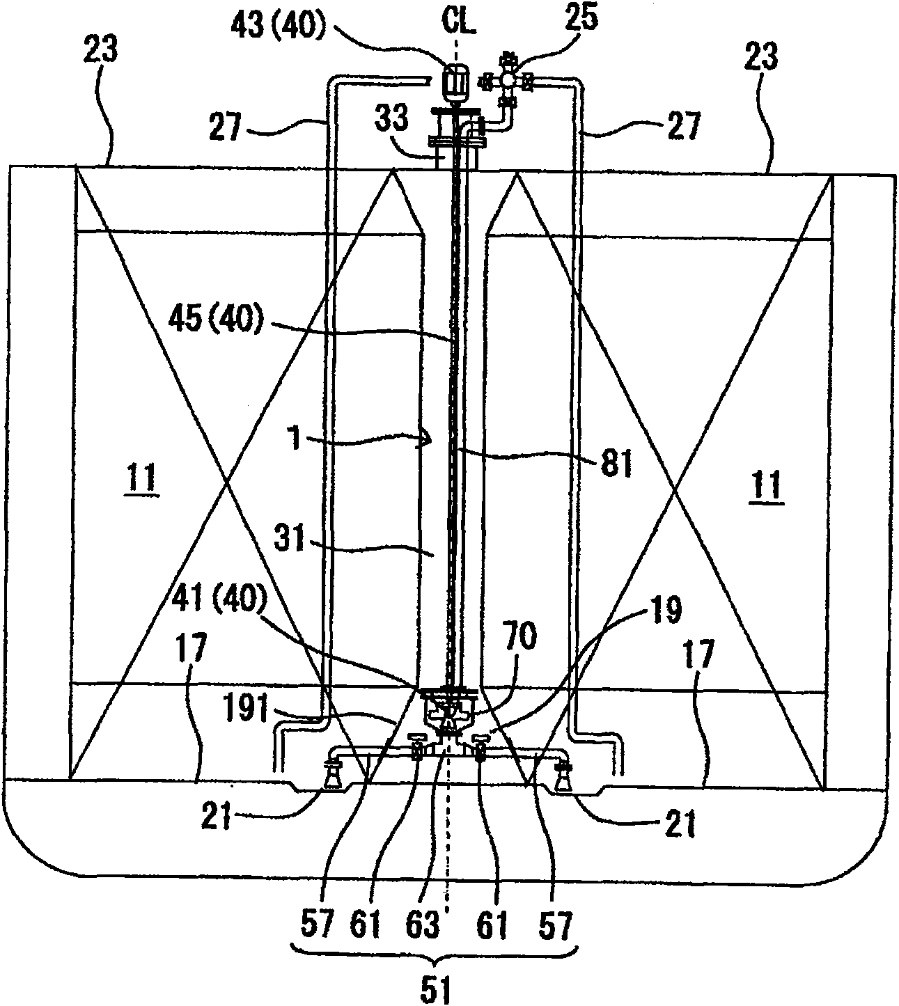
[0086] Next, based on Figure 5 as well as Image 6 The cargo pump device related to the second embodiment will be described. Since the structure of the cabin 11, the central partition 13, the transverse partition 15, the cargo pump room 31, and the hatch portion 33 are the same as those in the first embodiment, the description thereof will be omitted, and it is attached to the cargo pump device. The structure and effect of the residual oil recovery device of 2 are also the same as those of the first embodiment, so the description thereof will be omitted.

[0087] The cargo pump device 2 is mainly composed of a deep well pump 40 arranged in each cargo pump chamber 31, a cargo suction part 52 connected to the suction side of the deep well pump 40, and a cargo pump connected to the discharge side of the deep well pump 40. A discharge pipe 81 is formed.

[0088] The deep well pump 40 is composed of a motor part 43 and a pump part 41 connected to the motor part 43 via a drive sh...

Embodiment 3

[0096] Next, based on Figure 7 as well as Figure 8 The cargo pump device related to Embodiment 3 will be described. Since the structure of the cabin 11, central partition 13, transverse partition 15, cargo pump room 31, and hatch 33 is the same as that of Embodiment 1, its description will be omitted, and it is attached to the cargo pump device. The configuration and effects of the residual oil recovery device of 3 are also the same as those of Embodiment 1, so the description thereof will be omitted.

[0097] The cargo pump device 3 is mainly composed of a deep well pump 40 configured in each cargo pump chamber 31, a cargo suction portion 53 connected to the suction side of the deep well pump 40, and a cargo pump connected to the discharge side of the deep well pump 40. A discharge pipe 81 is formed.

[0098] The deep well pump 40 is composed of a motor part 43 and a pump part 41 connected to the motor part 43 via a drive shaft 45. The motor part 43 is fixed on the hatch ...


PUM


Abstract

A cargo pump apparatus is suitable for liquid cargo ships required to carry six to eight types of cargo and having a plurality of holds partitioned by a central bulkhead standing upright on a lower longitudinal stool and transverse bulkheads. Each cargo pump room is provided at an intersecting portion of the central bulkhead and one of the transverse bulkheads, and penetrates a hatch provided on an upper deck and the lower longitudinal stool. One deep well pump is provided in each cargo pump room. The suction side of the deep well pump is connected to a cargo suction portion which has an open end in the hold and penetrates the inclined wall of the lower longitudinal stool. The discharge side of the deep well pump is connected to a cargo discharge pipe connected to a manifold pipe laid on the upper deck through the cargo pump room.; Either the cargo suction portion in the cargo pump room is connected through an expansion pipe, or the deep well pump is secured through an expansion pipe.

Description

technical field [0001] The invention relates to a cargo pump device and a cargo pipeline on a liquid cargo transport ship, in particular to a cargo pump device and a cargo suction pipe used in a liquid cargo lifting and unloading system. Background technique [0002] In recent years, in order to be able to load and unload four types of cargo at the same time, a 50,000-ton liquid cargo ship has been built. Four cargo pumps are installed in the cargo pump room between the cargo cabin and the engine room, and the main branch (メインブランチ ) way of cargo piping. In addition, among liquid cargo ships having 12 to 16 cabins, independent cargo pumps (submersible pumps) are installed in each of the tanks. [0003] As a liquid cargo ship equipped with independent cargo pumps in each hold, for example, there is a liquid cargo ship disclosed in JP-A-2001-180576. [0004] The technology disclosed in Japanese Patent Application Laid-Open No. 2001-180576 aims to "provide a chemical tanker cap...

Claims


Application Information

Patent Timeline
Patent Type & Authority Patents(China)
IPC IPC(8): B63B27/24B63J99/00
CPCB63B11/02B63B27/24B63B25/08
Inventor 玉井康志重光健太郎
Owner SHIN KURUSHIMA DOCKYARD CO LTD
Why Eureka
Try Eureka