
Nailing gun

A nailing gun and gun nozzle technology, applied in the field of nailing guns, can solve the problems of inability to hit continuously, poor hit uniformity, short service life, etc. Effect

Inactive Publication Date: 2011-05-18
JIANGSU HEHUI POWER TOOLS CO LTD
View PDF5 Cites 12 Cited by
  • Summary
  • Abstract
  • Description
  • Claims
  • Application Information

AI Technical Summary

Problems solved by technology

The problem with this type of nailing gun is that the slider crank mechanism cannot achieve a real impact, and is essentially a "push" nailing mechanism, so the work efficiency of each nailing is not high; the second is that the motor is placed on the The front or rear side of the handle is connected with the transmission mechanism and occupies a large space, which makes the nailing gun bulky and not convenient to carry and operate.
Although this nail gun utilizes spring energy storage to realize instant hitting on nails, it can only click one by one and cannot hit continuously, so the working efficiency of long-term use is still not high; in addition, its motor is located under the gun head. In the casing, it is completely separated from the handle, and there is still the problem of not compact structure
[0005] There is also a nail driving structure using spring energy storage and impact block inertia. Although the structure is relatively compact and the nails are driven continuously, the nail driving force is small and cannot effectively hit various types of nails. It is only suitable for relatively small nails; and this structure The spring in the battery is prone to fatigue failure, short service life, poor strike uniformity, low energy conversion efficiency, fast battery energy consumption, and a small number of nails in a single battery pack

Method used


Image

  • Nailing gun
  • Nailing gun
  • Nailing gun

Examples


Embodiment Construction

[0019] Below in conjunction with accompanying drawing, nailing gun of the present invention will be further described.

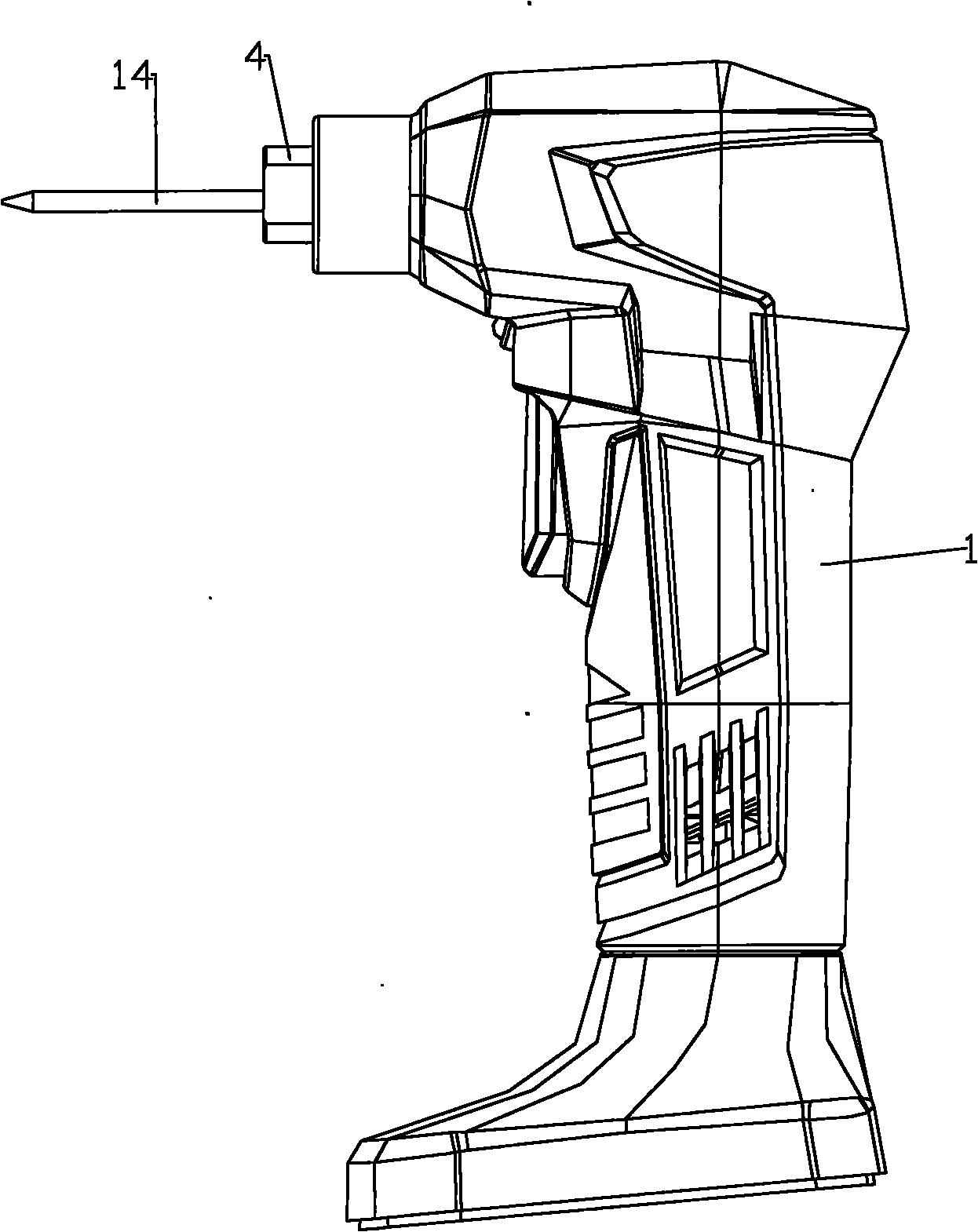
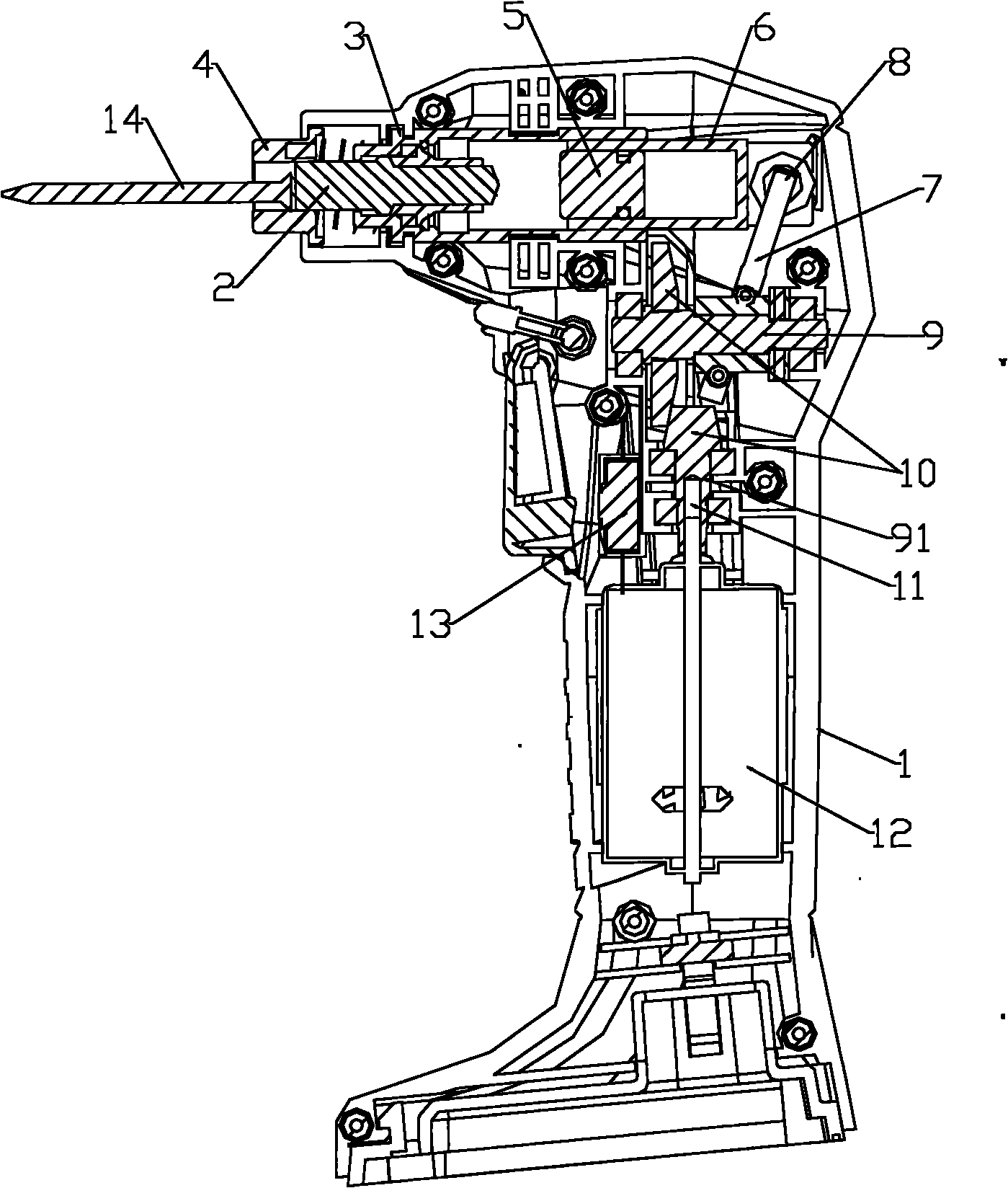
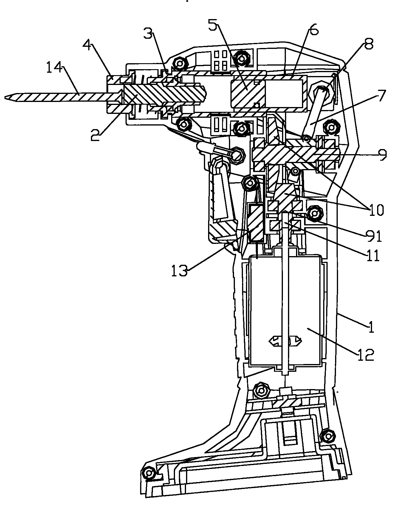
[0020] Such as Figure 1-2 As shown, the nailing gun of the present invention includes a casing cavity and a motor 12. The casing cavity is formed by combining the left and right halves of the casing 1, and the main body of the casing cavity forms a vertical handle. , the upper end of the main part of the casing cavity protrudes forward to form a transverse gun mouth, and a cylinder block 3 is installed on the upper end of the main part of the casing cavity, and the cylinder block 3 is provided with an air inlet and two A vent hole, the casing cavity is provided with a rotation-linear motion conversion transmission mechanism, the motor 12 is connected with the piston 6 through the rotation-linear motion conversion transmission mechanism, and the nailing pin 2 of the top nail 14 is provided in the gun mouth, The nailing pin 2 is arranged horizontally, and is...


PUM


Abstract

The invention discloses a nailing gun which comprises a shell cavity and a motor, wherein the shell cavity is formed by carrying out involution on a left half shell and a right half shell; a rotary-linear motion conversion transmission mechanism is arranged in the shell cavity; the motor is connected with a piston through the rotary-linear motion conversion transmission mechanism; a nail striking pin for nailing is arranged in a gun mouth of the nailing gun and fixed in a cylinder body; the piston is mounted in the cylinder body; an axial cavity with an opening at one end of the axial cavity is arranged in the piston; an air hammer is mounted in the axial cavity of the piston; the gun mouth is also provided with a nail accommodating port formed by an indention structure; and the axis of the nail accommodating port is coaxial with that of the nail striking pin. By utilizing the structure provided by the invention, a continuous hammering function is realized in a compact space, and the energy utilization efficiency is improved; continuous efficient striking on a nail can be achieved, thereby effectively avoiding the trouble that the nail cannot be nailed by a single-shot nailing gun under certain working conditions; and moreover, as the nail is stricken by the air hammer, the striking force is great.

Description

technical field [0001] The invention relates to the technical field of electric tools, in particular to a nail gun. Background technique [0002] A staple gun is a commonly used hand-held tool with a wide variety. According to the power source, nail guns can be divided into two categories: pneumatic and electric. Among them, the pneumatic nailing gun must have a compressed air source, so its use is limited. The basic structure status of electric nail gun: [0003] A kind of nail gun with a slider crank mechanism as a rotary-linear motion transmission mechanism and a battery as a power supply. The problem with this type of nailing gun is that the slider crank mechanism cannot achieve a real impact, and is essentially a "push" nailing mechanism, so the work efficiency of each nailing is not high; the second is that the motor is placed on the The front or rear side of the handle is connected with the transmission mechanism and occupies a large space, which makes the nailing...

Claims


Application Information

Patent Timeline
IPC IPC(8): B25C1/06
Inventor 阳小飞
Owner JIANGSU HEHUI POWER TOOLS CO LTD
Learn More