
Integration construction between a boiler and a steam turbine and method in preheating of the supply water for a steam turbine and in its control

a technology of integrated construction and steam turbine, which is applied in the direction of steam engine plants, feed-water heaters, lighting and heating apparatus, etc., can solve the problems of deteriorating the inability of soda recovery boilers to provide flue gas/air heat exchangers, and the low electricity power obtained from the back-pressure turbine, so as to reduce the impact of electricity production and improve the efficiency of the boiler

Inactive Publication Date: 2005-10-04
FORTUM OY
View PDF15 Cites 3 Cited by
  • Summary
  • Abstract
  • Description
  • Claims
  • Application Information

AI Technical Summary

Benefits of technology

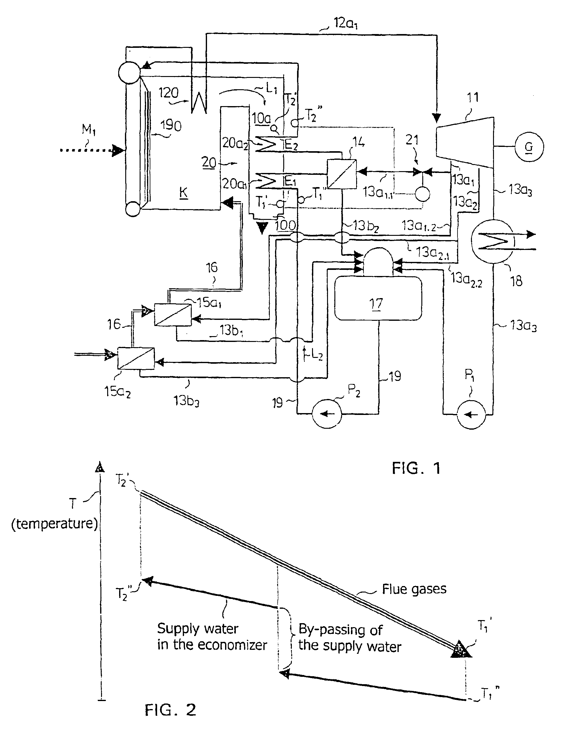
[0015]It is disclosed in the present application that by limiting the amount of bled steam of the preheater in the divided economizer, the integration degree of the steam turbine process can be controlled. The preheating is limited by the boiling temperature of the hottest economizer, and the lower limit is the closing of the bled. The method of control exerts an efficient impact on the electricity production but it slightly deteriorates the efficiency of the boiler when the bled steam use exceeds the scheduled value. A change in the degree of integration is of the order 10%. A change in the efficiency of the boiler is 2 to 3% at most.

Problems solved by technology

The method of control exerts an efficient impact on the electricity production but it slightly deteriorates the efficiency of the boiler when the bled steam use exceeds the scheduled value.
Particularly when a soda recovery boiler is in question, the flue gases are highly soiling and corroding, and therefore, the soda recovery boilers cannot be provided with a flue-gas / air heat exchanger.
The above integration is not optimal considering the steam turbine process and therefore, the electricity power obtained from a back-pressure turbine remains low.

Method used


Image

  • Integration construction between a boiler and a steam turbine and method in preheating of the supply water for a steam turbine and in its control
  • Integration construction between a boiler and a steam turbine and method in preheating of the supply water for a steam turbine and in its control

Examples


Embodiment Construction

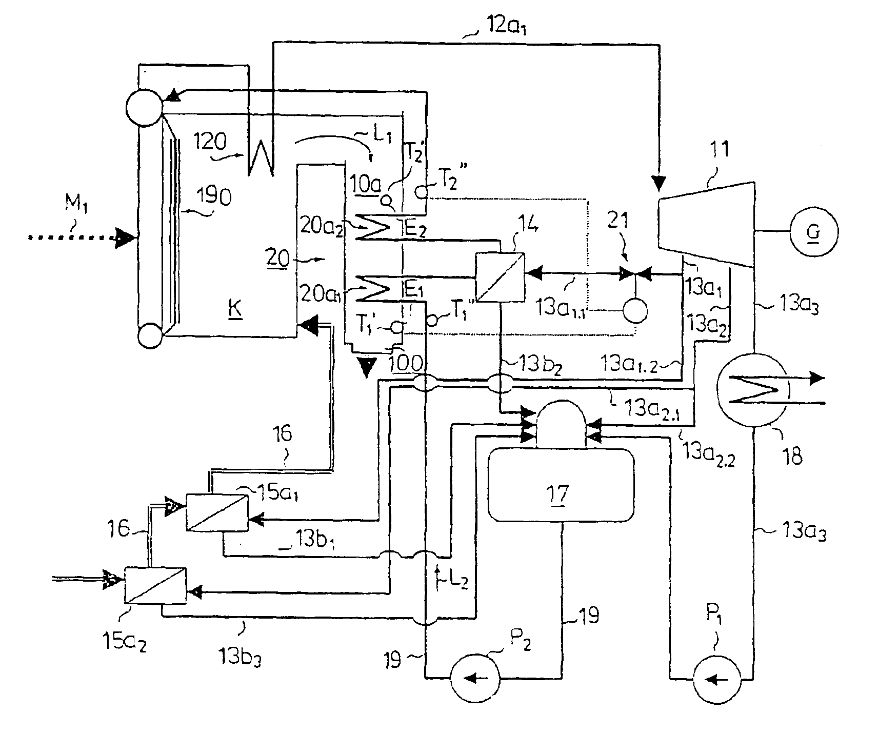
[0026]FIG. 1 presents an integration construction of the invention between a steam boiler and a steam turbine, comprising a steam boiler, such as soda recovery boiler, to which fuel is brought as shown by arrow M1. The boiler is indicated by reference numeral 10. The evaporator is indicated by reference numeral 190 and the superheater thereafter in a connector 12a1 by reference numeral 120. The flue gases are discharged during a second draught 10a from the boiler 10 through a smoke stack 100 into the outside air as shown by arrow L1. The second draught 10a is the part of the boiler which comprises heat faces prior to the smoke stack 100. Superheated steam is conducted to the steam turbine 11 along the connector 12a1 and the steam turbine 11 is arranged to rotate a generator G producing electricity. From the steam turbine 11, connectors 13a1 and 13a2 are provided for bled steams and a connector 13a3 into a condensator for exit steams or back-pressure steam travelling into an industri...


PUM


Abstract

The present invention concerns an integration construction between a steam boiler provided with a combustion chamber and a steam turbine. The steam is conducted from the steam boiler (10) along a connector to the steam turbine (11) for rotating an electric generator (K) producing electricity. The supply water circulated via the steam boiler (10) is vaporized in a vaporizer (190) located in the steam boiler (10) and superheated in a superheater (120). The supply water is conducted into the boiler through an economizer (20) acting as a heat exchanger, where heat is transferred from the flue gases of the boiler into the supply water. The economizer (20) is provided with at least two sections, comprising at least one first economizer section (20a1) and at least one second economizer section (20a2). The supply water is conducted from the first economizer section (20a1) to a supply water preheater formed from a heat exchanger (14), where thermal energy is transferred from bled steams of the steam turbine either directly or via a medium, advantageously water, into the supply water. The supply water preheated with bled steams of the steam turbine is conducted in the steam boiler (10) to the second economizer section (20a2) and further to the vaporizer (190) and the superheater (120) and therethrough, in the form of steam, to the steam turbine. In the integration construction, the temperature of the supply water is raised continuously as the supply water is flowing in the first economizer section (20a1) and from the first economizer section (20a1) to the supply water preheater (14) and threthrough, to the second economizer section (20a2). The connector (13a1.1) leading to the supply water preheater (14) comprises a valve (21) for controlling the bled-steam.

Description

FIELD OF THE INVENTION[0001]The present invention relates to an integration construction between a boiler and a steam turbine and a method in preheating the supply water for a steam turbine and in its control.BACKGROUND OF THE INVENTION[0002]The last heat face of a steam boiler before the smoke stack is either a flue-gas / air heat exchanger or an economizer. In the present application, a flue-gas / air heat exchanger is understood as a heat exchanger between flue gas and combustion air, in which the heat is transferred from the flue gas into the combustion air to preheat the combustion air. In the present application, an economizer is understood as a heat exchanger in which thermal energy is transferred from the flue gases into the supply water.[0003]When a flue-gas / air heat exchanger is used, the supply water for the boiler can be preheated by means of bled steam from a steam turbine, whereby the efficiency of the steam turbine process is enhanced. A flue-gas / air heat exchanger, i.e. ...

Claims


Application Information

Patent Timeline
Patent Type & Authority Patents(United States)
IPC IPC(8): F22D1/40F22D1/00
CPCF22D1/40
Inventor RAIKO, MARKKU
Owner FORTUM OY
Learn More