
Curved surface energy dissipation wall for hydraulic engineering

A water conservancy engineering and curved surface technology, which is applied in water conservancy engineering, sea area engineering, coastline protection, etc., can solve the problems of reducing the impact resistance of components, weakening the water flow momentum of components, deflecting components, etc., achieving efficient impact, increasing contact area, avoid skewed effects

Active Publication Date: 2020-07-14
KUNMING UNIV OF SCI & TECH
View PDF7 Cites 4 Cited by
  • Summary
  • Abstract
  • Description
  • Claims
  • Application Information

AI Technical Summary

Problems solved by technology

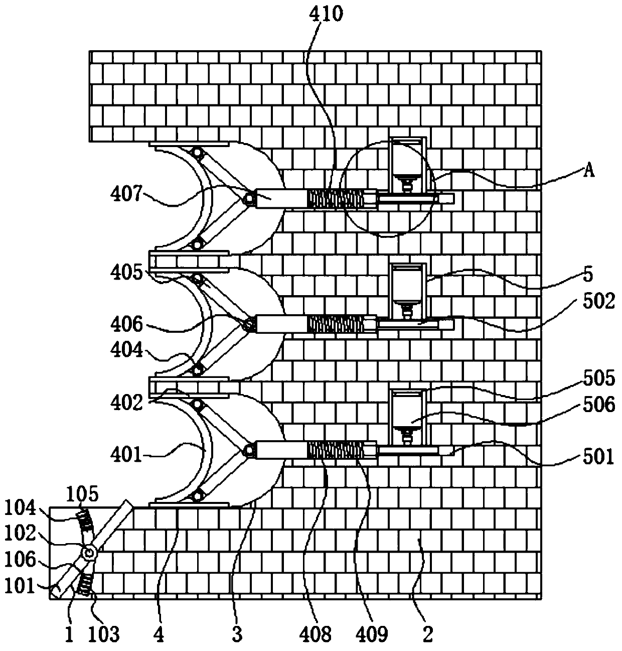
[0004] Aiming at the deficiencies of the prior art, the present invention provides a curved energy-dissipating wall for water conservancy engineering, which solves the problem that the internal components of the curved energy-dissipating wall of hydraulic engineering proposed in the above-mentioned background technology are impacted by water flow, which may easily lead to deflection of the components. , reducing the impact resistance of the components will lead to damage to the components, affecting the weakening effect of the components on the impact of the water flow, as well as the potential energy generated by the water flow, resulting in a lot of waste and the problem that it cannot be effectively used

Method used


Image

  • Curved surface energy dissipation wall for hydraulic engineering
  • Curved surface energy dissipation wall for hydraulic engineering
  • Curved surface energy dissipation wall for hydraulic engineering

Examples


Embodiment Construction

[0024] The following will clearly and completely describe the technical solutions in the embodiments of the present invention with reference to the accompanying drawings in the embodiments of the present invention. Obviously, the described embodiments are only some, not all, embodiments of the present invention.

[0025] In the description of the present invention, unless otherwise specified, the orientation or positional relationship indicated by the terms "upper", "lower" and the like are based on the orientation or positional relationship shown in the drawings, and are only for the convenience of describing the present invention and simplifying the description. It is not intended to indicate or imply that the referred device or element must have a particular orientation, be constructed in a particular orientation, and operate in a particular orientation, and thus should not be construed as limiting the invention.

[0026] In the description of the present invention, it shoul...


PUM


Abstract

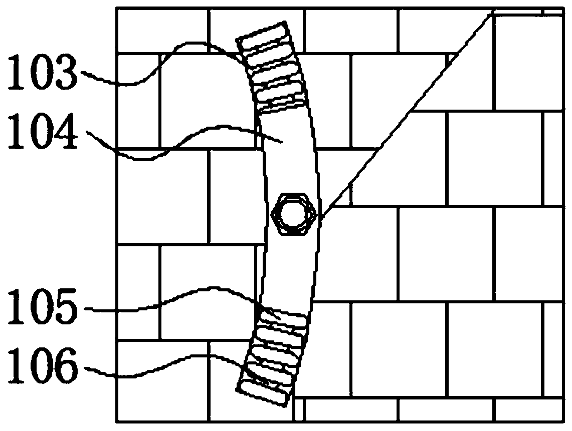
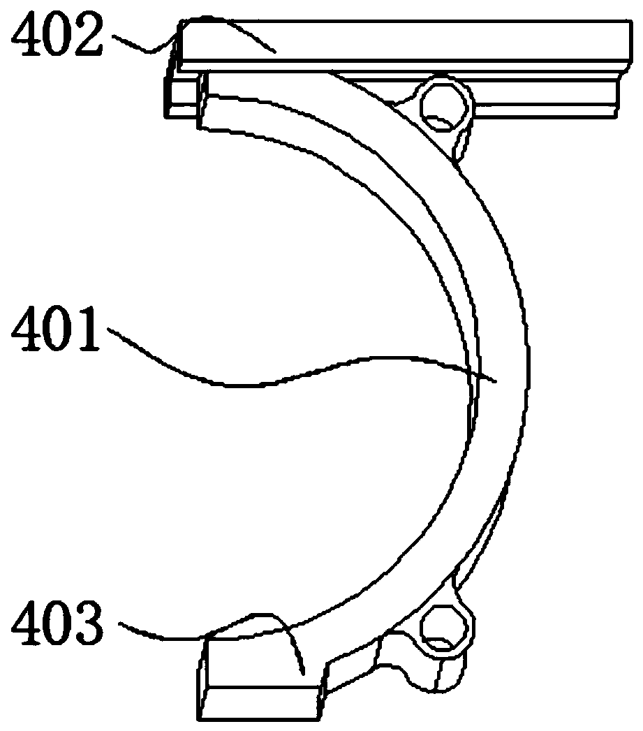
The invention relates to a curved surface energy dissipation wall for hydraulic engineering, and belongs to the technical field of hydraulic engineering. The curved surface energy dissipation wall comprises a flow guide mechanism and a buffer mechanism, a wall body is installed on one side of the flow guide mechanism, a curved surface groove is formed in the wall body, the buffer mechanism is located in the curved surface groove, and an energy storage mechanism is installed on one side of the curved surface groove. According to the curved surface energy dissipation wall for hydraulic engineering, connecting sliding blocks and limiting sliding grooves are arranged, the contact area between water flow and arc plates can be effectively increased through the arc-shaped structures of the arc plates, the arc plates can effectively move in the horizontal center line direction of the limiting sliding grooves through the connecting sliding blocks, and the moving tracks of the connecting slidingblocks can be effectively controlled; and through symmetrical distribution of the connecting sliding blocks and the limiting sliding grooves, the arc plates can be effectively prevented from deflecting, so that the arc plates efficiently bear impact of water flow, and the situation that the impact resistance of the arc plates is reduced due to deflection of the arc plates can be effectively avoided.

Description

technical field [0001] The invention relates to a curved energy-dissipating wall for water conservancy projects, which belongs to the technical field of water conservancy projects. Background technique [0002] Water conservancy engineering is a general term for various engineering constructions built to control, utilize and protect surface and underground water resources and the environment. Flood control, waterlogging, irrigation, power generation, water supply, reclamation, soil and water conservation, resettlement, water resource protection and other projects (including new construction, expansion, reconstruction, reinforcement, restoration) and their supporting and ancillary projects are collectively referred to. It is a project built to control and allocate surface water and groundwater in nature to achieve the purpose of eliminating harm and rejuvenating profits. Also known as water engineering. Water is an indispensable precious resource for human production and li...

Claims


Application Information

Patent Timeline
Patent Type & Authority Applications(China)
IPC IPC(8): E02B8/06
CPCE02B8/06
Inventor 张朔刘小刚吴朗李慧永钱龙孙文艳
Owner KUNMING UNIV OF SCI & TECH
Learn More