Laminating method of liquid optical cement laminating machine

A technology of optical glue and laminating machine, which is applied in the direction of chemical instruments and methods, static indicators, lamination devices, etc., can solve the problems of poor utilization of factory space and occupancy, and achieve simple and easy monitoring and management, reducing space, The effect of improving space utilization

Inactive Publication Date: 2011-05-18
正闵机电股份有限公司
View PDF5 Cites 15 Cited by
  • Summary
  • Abstract
  • Description
  • Claims
  • Application Information

AI Technical Summary

Problems solved by technology

But in this way, the length and width of the interior space of the plant must be greater than the length of the strip-shaped machine, so that the strip-shaped machine will occupy most of the space in the plant, resulting in poor utilization of plant space. One problem needs to be further improved

Method used


Image

  • Laminating method of liquid optical cement laminating machine
  • Laminating method of liquid optical cement laminating machine
  • Laminating method of liquid optical cement laminating machine

Examples


Embodiment Construction

[0042] The technical means adopted by the present invention in order to realize the intended invention purpose will be further elaborated below with reference to the accompanying drawings and preferred embodiments of the present invention.

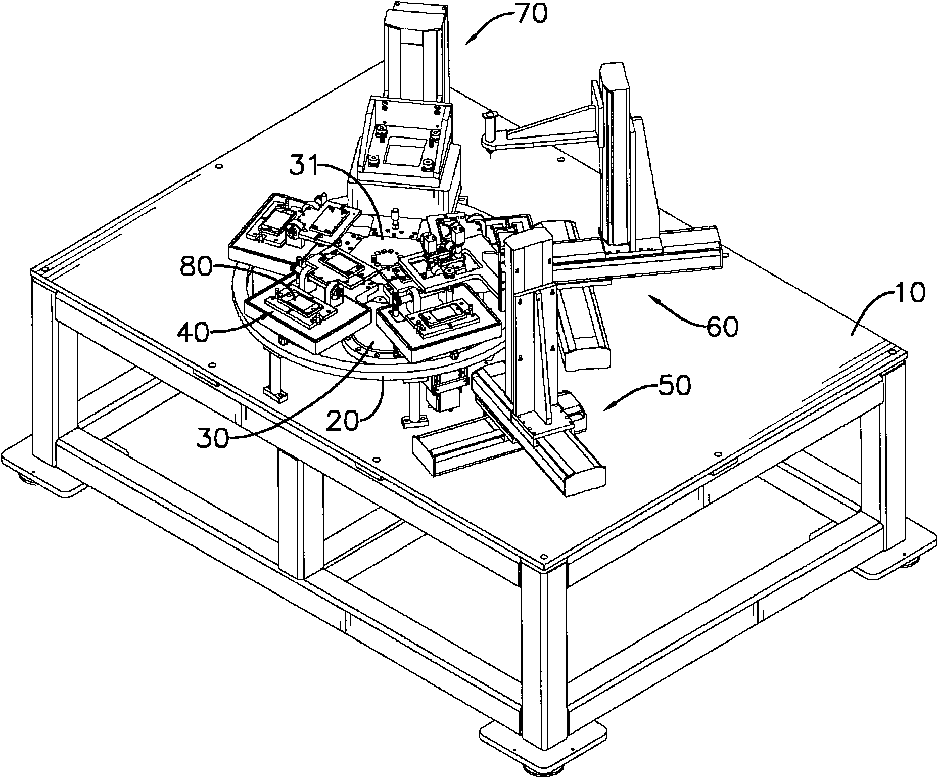
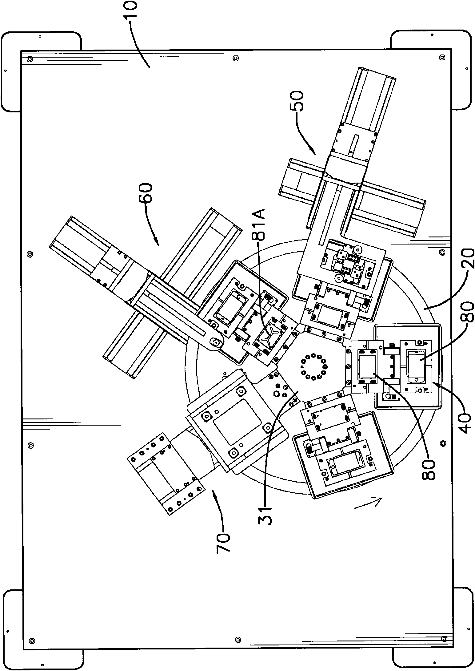
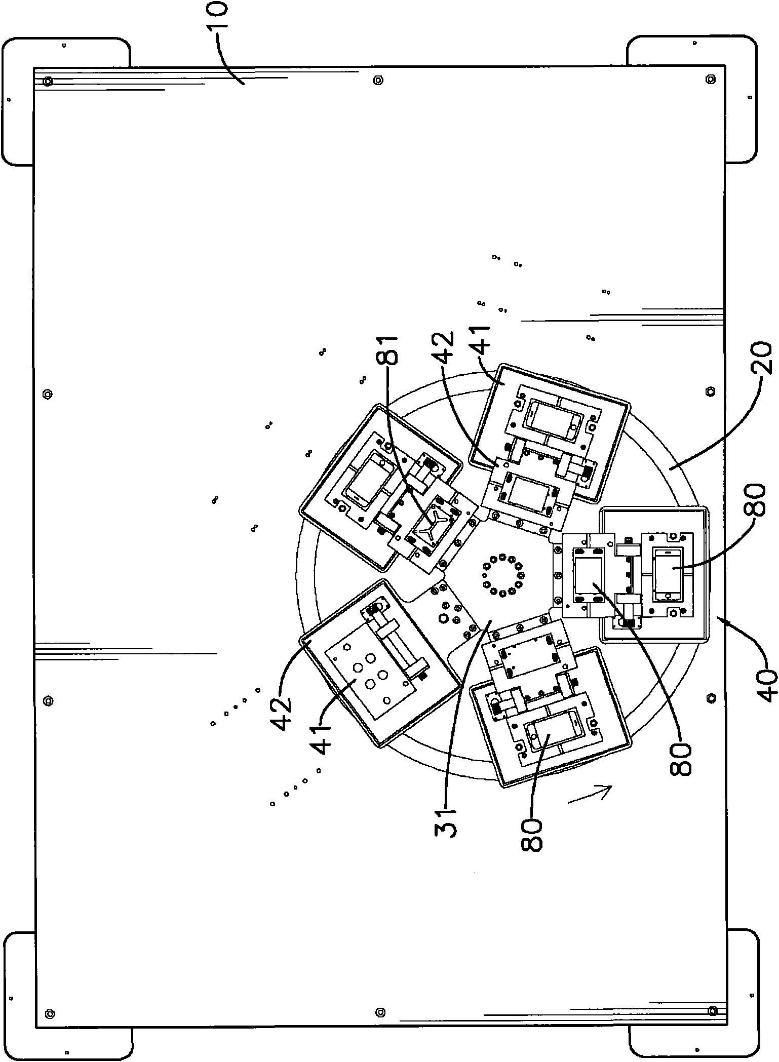
[0043] Figure 1 to Figure 3 It represents a specific embodiment in which the laminating method of the present invention is applied to a liquid optical glue laminating machine, wherein the laminating machine has a machine table (10), a fixed frame (20), a rotary drive device (30), a plurality of carrying device (40), detection device (50), dispensing device (60) and vacuum pressing device (70), the fixed frame (20) is a hollow ring frame body, and is fixed on the machine platform (10) , the rotary driving device (30) is assembled on the machine platform (10), and is located inside the hollow frame body of the fixed frame (20), and the top of the rotary driving device (30) is provided with a rotary platform (31 ), the carrying device (40) ...


PUM


Abstract

The invention discloses a laminating method of a liquid optical cement laminating machine, wherein the liquid optical cement laminating machine implementing the laminating method drives a base plate of a touch panel on a circular machine table to rotate in a rating manner, and then the annularly moving base plate is respectively and sequentially subjected to the process flows of a detection step, a cement dispensing step, a laminating step, an objects taking out step and the like. The invention is convenient for operators to manage and control and effectively reduce the space occupied by processing devices so as to play the role of improving the space utilization rate of factory buildings.

Description

technical field [0001] The invention relates to a laminating method of a liquid optical glue laminating machine, in particular to a laminating method in which each laminating processing step is designed at the peripheral edge of a circular machine table, and the objects to be processed are sequentially processed in a circular moving manner . Background technique [0002] With the vigorous development of the electronic industry, various electronic devices are not only becoming more and more diversified and complex in function, but also developing in the direction and concept of light, thin, short, and small. Among them, the touch panel also has The two functions of liquid crystal display and touch input enable users to control and operate various electronic devices by touching the panel, thereby reducing the volume occupied by the electronic device and improving the practicability of the electronic device. [0003] The above-mentioned touch panel mainly includes two transpar...

Claims


Application Information

Patent Timeline
Patent Type & Authority Applications(China)
IPC IPC(8): B32B37/12B32B37/10B32B38/18G02F1/133
Inventor 刘美云
Owner 正闵机电股份有限公司
Why Eureka
Try Eureka