Control method for descending movable arm of excavator

A control method and technology of motorized arms, which are applied in the direction of mechanically driven excavators/dredgers, etc., can solve the problems of uncomfortable, strong shaking or shaking, and not very good for the operator of the excavator, and achieve a simple and convenient structure. Descent speed, easy to achieve effect

Inactive Publication Date: 2011-05-18
SANY HEAVY MACHINERY
View PDF6 Cites 9 Cited by
  • Summary
  • Abstract
  • Description
  • Claims
  • Application Information

AI Technical Summary

Problems solved by technology

[0004] The action of the working device of the hydraulic excavator is realized by the combined movement distance between the boom, stick and bucket. The actions of these parts are all realized by the hydraulic oil provided by the hydraulic control circuit of the excavator to drive the hydraulic cylinders of the corresponding parts. However, during this series of operations, due to the fast oil supply and return speed of the hydraulic control circuit, the excavator will have a large impact when changing the operation action, and the whole machine will have strong vibration or shaking Wait for discomfort, which is quite uncomfortable for the operator of the excavator, and at the same time, the severe shaking will also damage the whole machine
At present, the method to solve the impact of the excavator working device is mainly to install a buffer device at the end of the hydraulic cylinder of each working device to prevent the shock phenomenon after the hydraulic cylinder works to the end. Although this method can solve the problem of boom cylinder extension and stick, The impact caused by the extension and retraction of the bucket cylinder, but it is not very effective in solving the impact when the boom cylinder is retracted and the boom is lowered

Method used


Image

  • Control method for descending movable arm of excavator
  • Control method for descending movable arm of excavator
  • Control method for descending movable arm of excavator

Examples


Embodiment 1

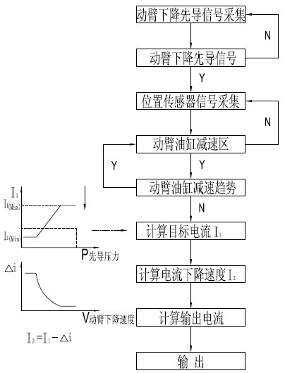
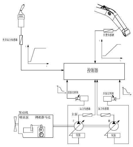
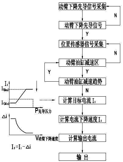
[0016] Embodiment one: see figure 1 , 2 As shown, a control method for the lowering of the boom of the excavator uses the pilot pressure sensor installed in the hydraulic control circuit to detect the action of the operating handle. When the operating handle controls the lowering of the boom, the position sensor installed on the boom The position of the boom cylinder is detected, and the speed of the boom at this time is obtained through logical operation according to the position of the boom cylinder, the oil supply amount of the boom cylinder is controlled, and the lowering speed of the boom is controlled.

[0017] When using this method, take an excavator working on a construction site as an example. When the operator of the excavator pulls the handle of the boom, the controller collects signals from the pilot pressure sensor. If the pilot signal for lowering the boom is not collected, continue On the contrary, if the signal is collected, the controller will collect the si...


PUM


Abstract

The invention discloses a control method for descending a movable arm of an excavator, which is characterized by comprising the following steps of: detecting the actions of an operating handle through a pilot pressure sensor arranged in a hydraulic control loop; when the operating handle controls the movable arm to descend, detecting the position of a movable arm cylinder through a position sensor installed on the movable arm; carrying out logical operation according to the position of the movable arm cylinder to obtain the speed of the movable arm at the moment; and controlling the oil supply of the movable arm cylinder and the descending speed of the movable arm. In the invention, the actions of the operating handle are detected through the pilot pressure sensor, the position of the movable arm cylinder is detected through the position sensor, and the descending speed of the movable arm is obtained, thereby the oil supply of the movable arm cylinder is controlled and the descending speed of the movable arm is controlled to further avoid impact generation due to too rapid descending of the movable arm.

Description

technical field [0001] The invention relates to a control method of an excavator, in particular to a control method for lowering the arm of the excavator. Background technique [0002] In daily construction production, the excavator is a commonly used construction machine. The main purpose of the excavator is to extract materials from the ground and transfer them to the unloading point. The excavator is a hydraulic excavator, which has the advantages of flexible construction and high efficiency, so it is widely used in foundation excavation of housing construction and cleaning after completion, urban pipeline laying, farmland water conservancy construction and other occasions. [0003] An excavator is generally composed of a working device, a slewing device, a cab, a traveling device, and a hydraulic control device. The slewing device and the walking device are the collective of the excavator, the working device is transferred to the slewing device, and the slewing device i...

Claims


Application Information

Patent Timeline
Patent Type & Authority Applications(China)
IPC IPC(8): E02F3/43
Inventor 戴晴华涂晓丹
Owner SANY HEAVY MACHINERY
Why Eureka
Try Eureka