Compressor

A technology for a compressor and a compression mechanism, which is applied in the field of compressors, can solve the problems of reduced reliability of compressors, reduced heat exchange capacity of heat exchangers, etc., and achieves the effect of high oil separation effect.

Active Publication Date: 2013-12-25
MITSUBISHI ELECTRIC CORP
View PDF2 Cites 2 Cited by
  • Summary
  • Abstract
  • Description
  • Claims
  • Application Information

AI Technical Summary

Problems solved by technology

If the refrigerating machine oil is carried out to the outside of the compressor together with the refrigerant, the refrigerating machine oil in the compressor will decrease, the supply of refrigerating machine oil to the compression mechanism will be insufficient, and the reliability of the compressor will decrease.
In addition, if the refrigerating machine oil brought out of the compressor together with the refrigerant adheres to the heat exchanger, the heat exchange capacity of the heat exchanger will also decrease.

Method used


Image

  • Compressor
  • Compressor
  • Compressor

Examples


Embodiment approach

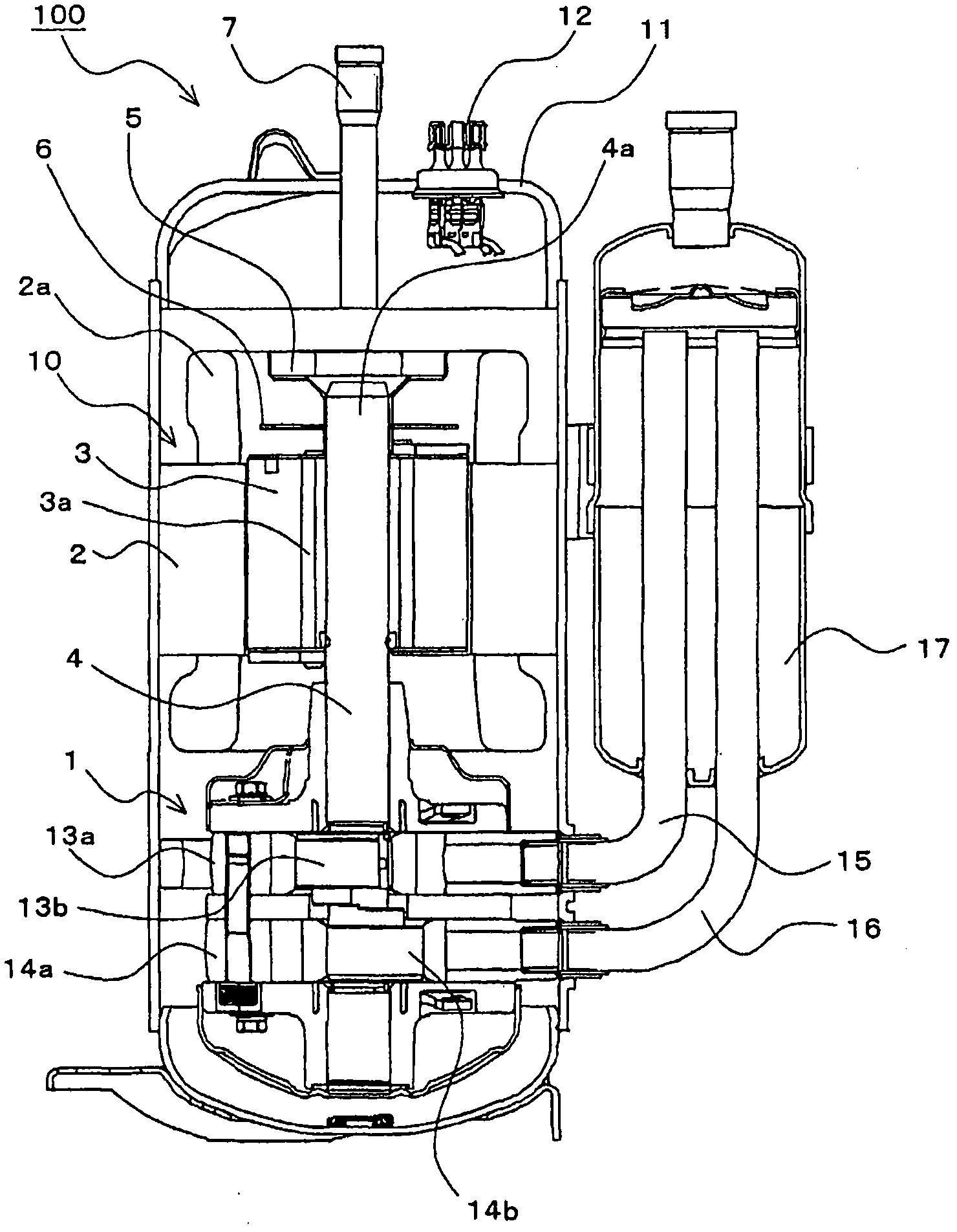
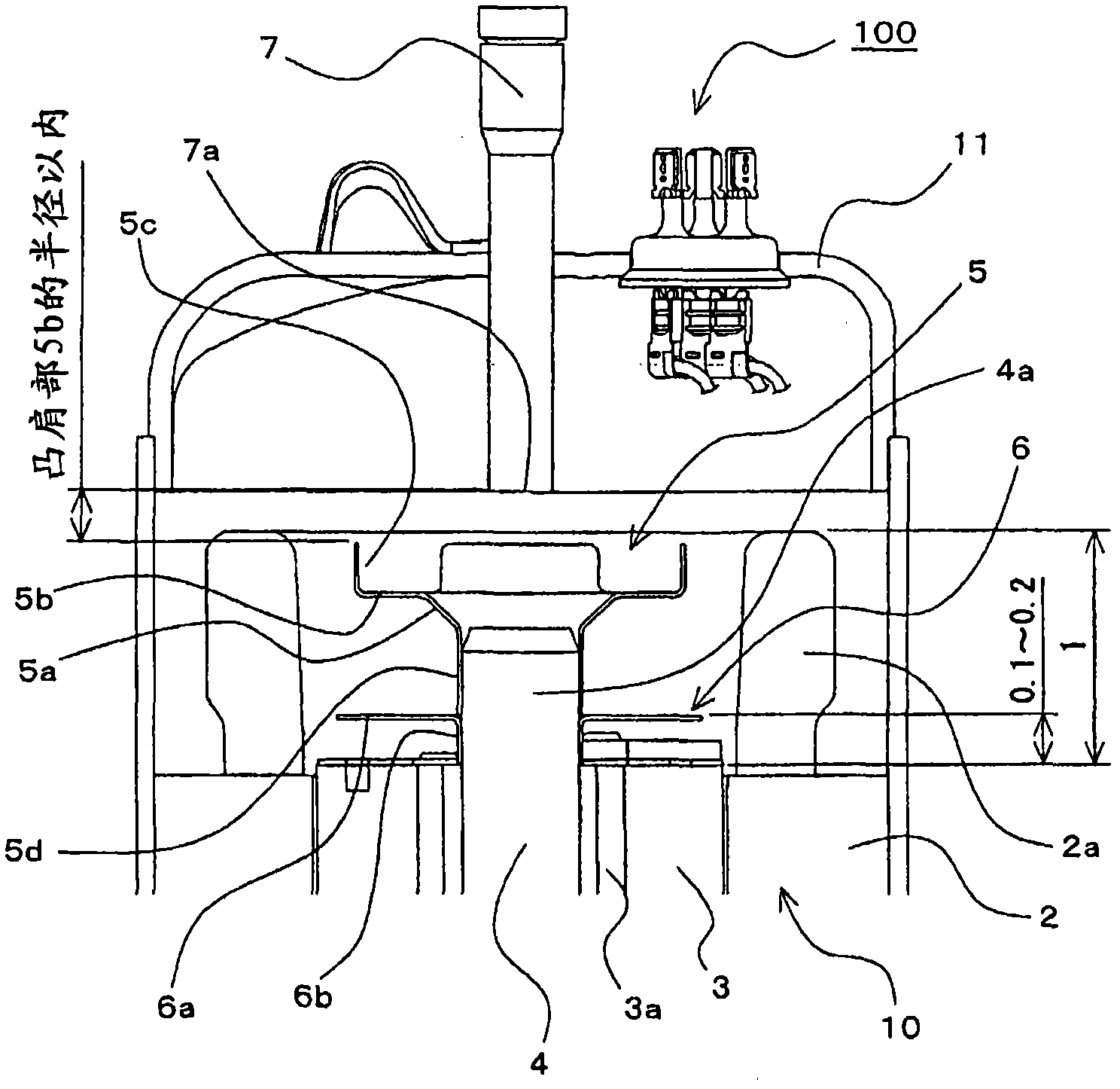
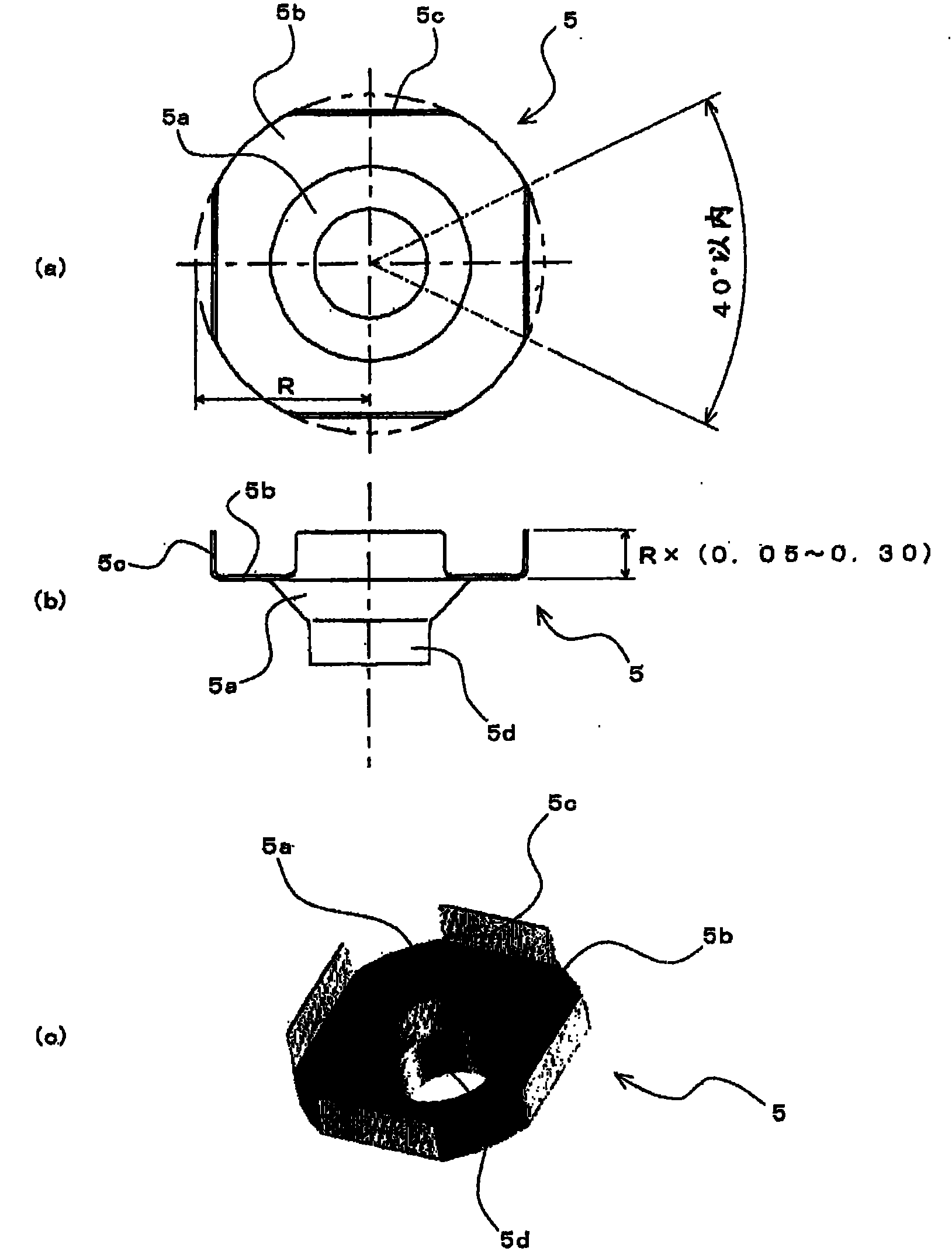
[0020] figure 1 It is a schematic longitudinal sectional view of the compressor according to the embodiment of the present invention. figure 2 to represent figure 1 It is an enlarged view of main parts near the upper part of the shown compressor. in addition, image 3 It is a detailed view showing the first oil separation member provided in the compressor. and, image 3 (a) shows a plan view of the first oil separation member, image 3 (b) shows a side view of the first oil separation member, image 3 (c) shows a perspective view of the first oil separation member. Below, according to these Figure 1 ~ Figure 3 The compressor 100 of this embodiment will be described.

[0021] The compressor 100 sucks in the refrigerant circulating in the refrigeration cycle, compresses it, and discharges it in a state of high temperature and high pressure. The compressor 100 is a hermetic compressor, and a compression mechanism 1 , a motor unit 10 , and the like are provided in a su...


PUM


Abstract

The invention provides a compressor with an oil separation effect better than that of conventional compressors. A first oil separation member (5), disposed on a projecting part (4a) of a driving shaft (4) protruding from the upper part of a rotor (3), has a crossette part (5b) projected in the radius direction of the driving shaft. The crossette part (5b) is composed of annular plate members, and multiple portions of the periphery of the plate members are bended to form bending parts (5c), which have a polygonal shape in the top view.

Description

technical field [0001] The present invention relates to a compressor, and more particularly to a hermetic compressor provided with an oil separation member inside. Background technique [0002] A hermetic compressor stores refrigerating machine oil inside. When the compression mechanism is driven, this refrigerating machine oil is supplied to the compression mechanism, thereby preventing wear of the compression mechanism. Therefore, refrigerating machine oil is mixed into the refrigerant discharged from the compression mechanism. If the refrigerating machine oil is taken out of the compressor together with the refrigerant, the refrigerating machine oil in the compressor decreases, and the supply of the refrigerating machine oil to the compression mechanism becomes insufficient, thereby reducing the reliability of the compressor. In addition, if the refrigerating machine oil brought out of the compressor together with the refrigerant adheres to the heat exchanger, the heat ...

Claims


Application Information

Patent Timeline
Patent Type & Authority Patents(China)
IPC IPC(8): F04B39/04
CPCF04C18/356F04C23/008F04C29/026F04C29/028F04C2210/26F04C2240/40Y10S415/00Y10S417/902
Inventor 长泽宏树远藤胜巳
Owner MITSUBISHI ELECTRIC CORP
Why Eureka
Try Eureka