A horizontal oil separator

An oil separator and oil separation technology, used in refrigeration components, refrigerators, lighting and heating equipment, etc., can solve the problems of gas short circuit, deterioration of separation effect, insufficient centrifugal force, etc., to reduce requirements, improve oil separation effect, oil and gas Full effect of separation process

Active Publication Date: 2015-07-29
GUANGDONG SHENLING ENVIRONMENT SYST CO LTD
View PDF8 Cites 0 Cited by
  • Summary
  • Abstract
  • Description
  • Claims
  • Application Information

AI Technical Summary

Problems solved by technology

The utility model adopts two-stage oil separation. Firstly, the first-stage oil separation is realized through the wire mesh filter composed of expanded metal mesh, wire mesh blocks and baffles arranged around the refrigerant inlet pipe, and then through the upper suction baffle to realize the first-stage oil separation. The second oil separation, although the oil separation effect is good after the second oil separation, but the overall structure is more complicated, and the oil is separated by filtration first, and then the oil is separated by the baffle, and the oil separation by filtration is usually relatively small for smaller oil droplets. It is effective, but the gas-oil mixture just entered from the intake pipe contains a large amount of oil droplets, and the filter oil is immediately used to separate the oil, which affects the overall oil separation effect, and the inlet of this oil separator is very close to the filter device, so the gas Immediately hitting the filter screen after entering, it is easy to cause a short circuit of the gas, resulting in poor separation effect, and when the load decreases and the gas flow rate decreases, the centrifugal force is obviously insufficient, resulting in the deterioration of the separation effect
[0008] In addition, during use, the existing oil separator tends to cause uneven distribution of the mixture of refrigerated oil and refrigerant gas when it enters and exits the oil separator, resulting in an excessively high flow rate of the mixed gas in some areas, which affects the separation effect
[0009] In summary, for the oil separator of large-scale refrigeration units, there are few reports on the use of horizontal oil separators that combine centrifugal oil separation and filter oil separation.
Some other centrifugal oil separators are also equipped with a filter layer, but usually they have a small volume and a high cross-sectional flow rate, which only stabilizes the air flow and controls the direction of the gas flow, and its ability to separate small-diameter oil droplets is very limited.

Method used


Image

  • A horizontal oil separator
  • A horizontal oil separator
  • A horizontal oil separator

Examples


Embodiment Construction

[0029] The present invention will be further described below in conjunction with the accompanying drawings.

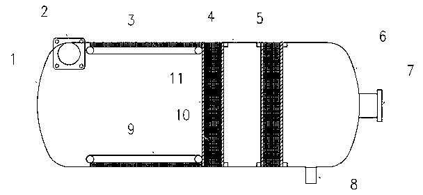
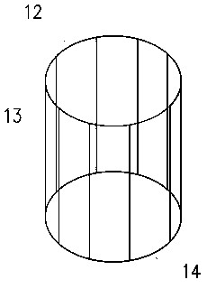
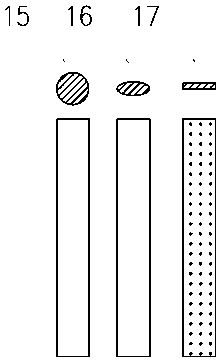
[0030] This implementation is applied to a horizontal oil separator of a large-scale flooded chiller. It consists of a cylinder body 4, a left head 1, a right head 6, two filter cores 10, an air inlet pipe 2, an air outlet pipe 7, an oil discharge pipe 8, a wall-attached wire mesh 3, and a spoiler 9. attached figure 1 The structure shown is installed. Wherein, the two ends of the cylinder 4 are welded with half standard elliptical heads 1 and 6 respectively to form a closed space, and the spoiler 9 is welded by the left circular ring 14, the right circular ring 12 and the spoiler 13. The diagram is attached figure 2 Shown, and the structure of the spoiler 13 is as attached image 3 Shown, can adopt multiple forms such as circular, oval, perforated plate, respectively as cylindrical spoiler 15, oval spoiler 16, perforated plate spoiler 17, perforated plate can ...


PUM


Abstract

The invention provides a horizontal type oil separator, which comprises a horizontal type barrel (4), an air inlet pipe (2), an air escape pipe (7), an oil discharge outlet (8) and an oil separation component, wherein the air inlet pipe (2) and the air escape pipe (7) are respectively arranged at the two ends of the barrel (4); the oil discharge outlet (8) is arranged at the bottom of the barrel (4); the oil separation component is arranged inside the barrel (4); and the oil separation component comprises a centrifugal oil separator and a filter type oil separator which are arranged along the front and back of gas stroke. According to the horizontal type oil separator, the structural feature of combining rotating centrifugal force and silk screen refined filtration is utilized, the kinetic energy of gas per se is fully utilized, most oil drops of large diameter are removed under the condition of not increasing resistance, the requirements of refined filtration sections are reduced, the oil-gas separation is more adequate, and the oil separation effect is improved under the condition of not increasing the size and the resistance of the barrel; and meanwhile, the centrifugal separation effect is intensified by utilizing a spoiler and an adherence silk screen.

Description

technical field [0001] The invention belongs to the field of refrigeration system accessories, in particular to a horizontal oil separator. Background technique [0002] Refrigeration oil is an indispensable lubricant in the compressor, which plays the role of reducing the wear of mechanical parts, reducing the friction of the mechanism, reducing the temperature and enhancing the sealing performance. When the refrigerating unit is running, the refrigerating oil inevitably enters the entire refrigerating system more or less with the refrigerant gas and participates in the refrigerating cycle. After the refrigerant oil enters the evaporator or condenser, a layer of oil film will be formed on the heat transfer surface. Since the thermal conductivity of this layer of oil film is small, this directly leads to the increase of the heat transfer resistance of the heat exchanger and affects the heat transfer performance. Studies have shown that in the evaporator of the refrigeration...

Claims


Application Information

Patent Timeline
Patent Type & Authority Patents(China)
IPC IPC(8): F25B43/02
Inventor 张学伟谢春晖潘展华欧阳惕陈华
Owner GUANGDONG SHENLING ENVIRONMENT SYST CO LTD
Why Eureka
Try Eureka