Floor heating thermostatic valve
A thermostatic valve, floor heating technology, applied in valve details, safety valve, balance valve and other directions, can solve the problem that the temperature control valve cannot adjust the set temperature value, cannot be applied to the water floor heating system, etc., to achieve a wide range of use and safe operation. High, easy-to-use effects
- Summary
- Abstract
- Description
- Claims
- Application Information
AI Technical Summary
Problems solved by technology
Method used
Image
Examples
Embodiment 1
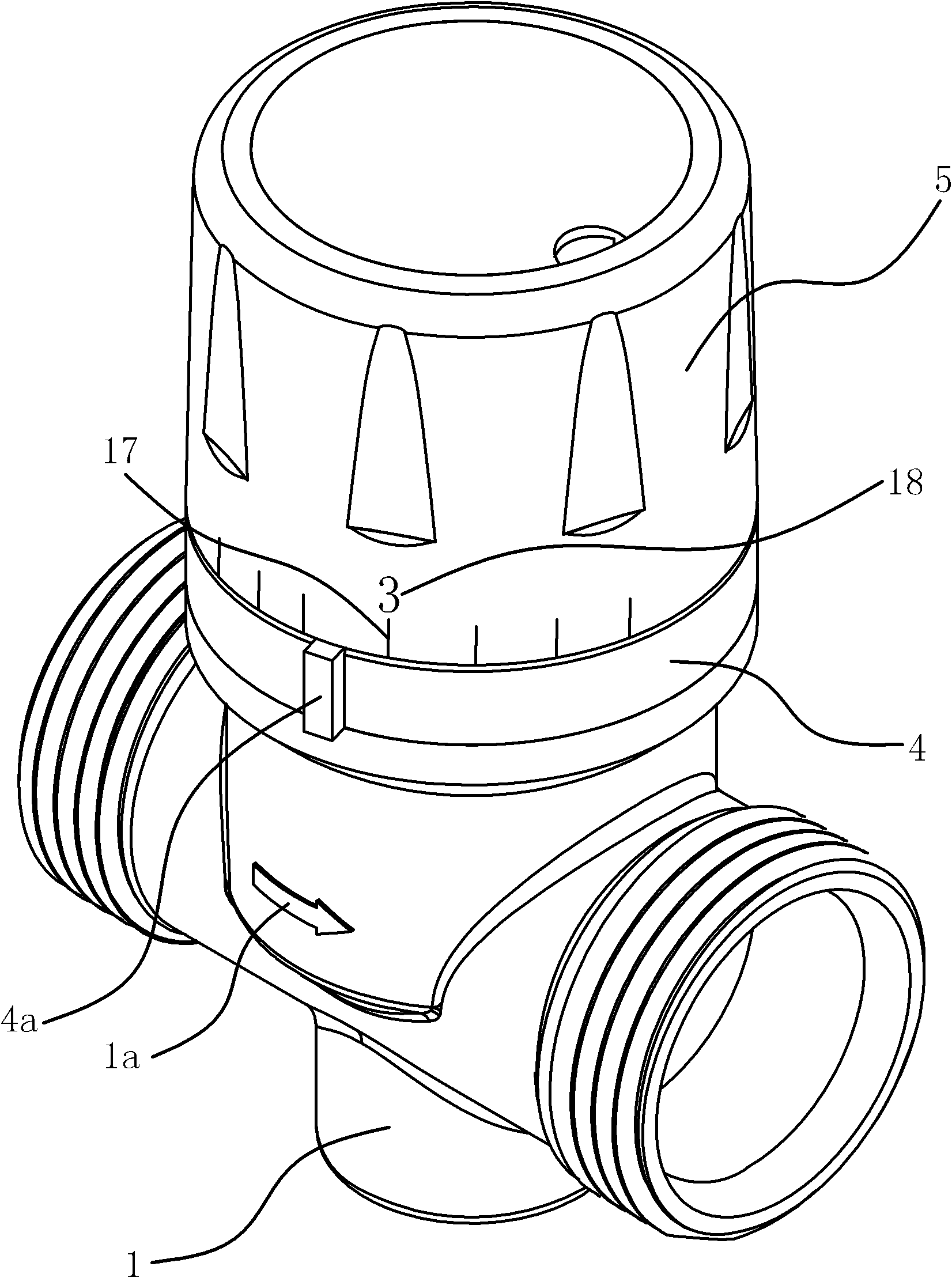
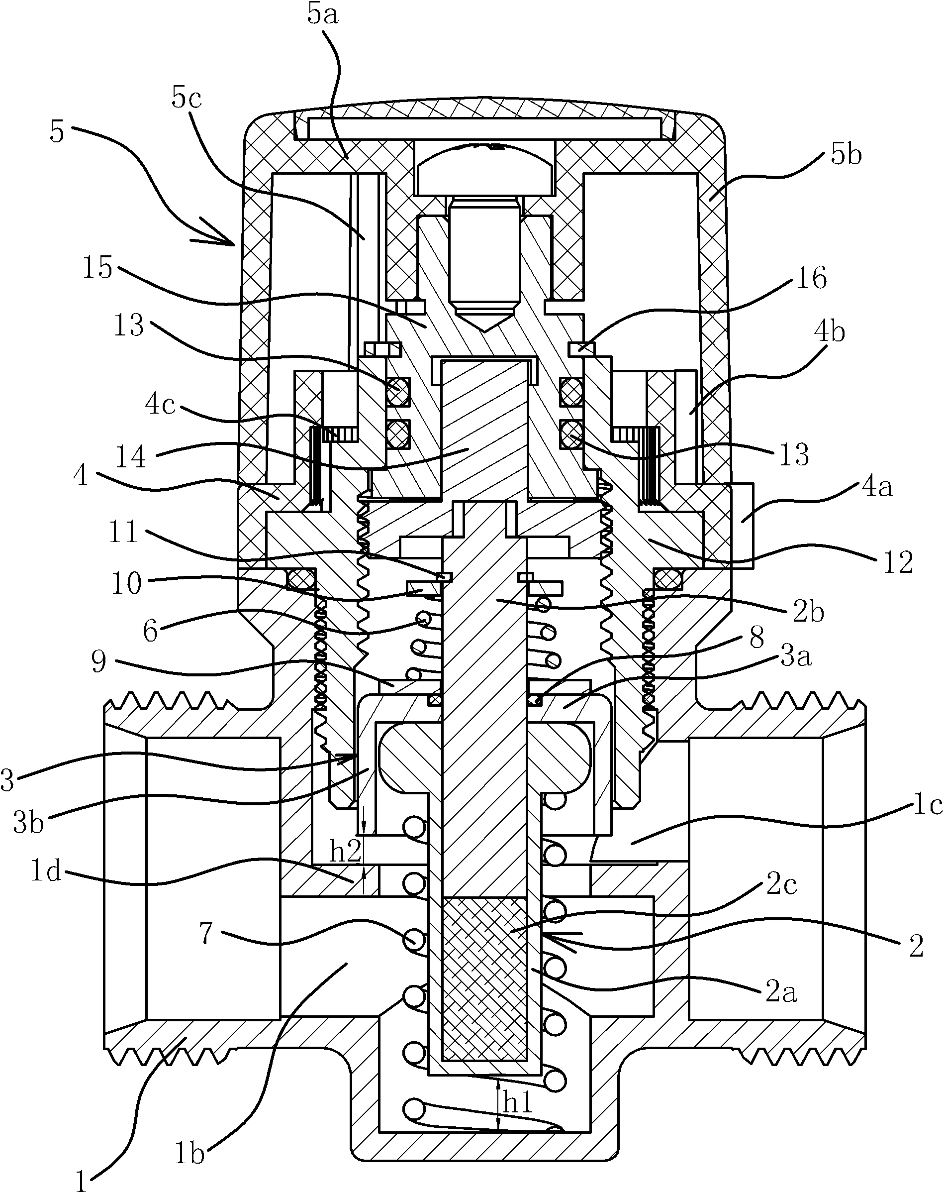
[0036] like Figure 1 to Figure 4 As shown, the local heating thermostatic valve includes a valve body 1, a temperature bulb 2, a valve core 3, a spring one 6, a spring two 7 and an adjustment mechanism.
[0037]Specifically, the valve body 1 has a sealing portion 1d inside, and further divides the inner chamber of the valve body 1 into a water inlet chamber 1b and a water outlet chamber 1c. On the outer wall of the valve body 1 there is an arrow 1a marking the direction of water flow.
[0038] The temperature bulb 2 includes a body 2a, a push rod 2b pierced on the body 2a, and a temperature-sensing medium 2c arranged in the body 2a. The inner end of the push rod 2b can abut against the temperature-sensing medium 2c, and the outer end passes through the body 2a. The temperature bulb 2 belongs to the prior art, and will not be described in detail here. The body 2a of the temperature bulb 2 is located in the water inlet chamber 1b, and the ejector rod 2b penetrates into the w...
Embodiment 2
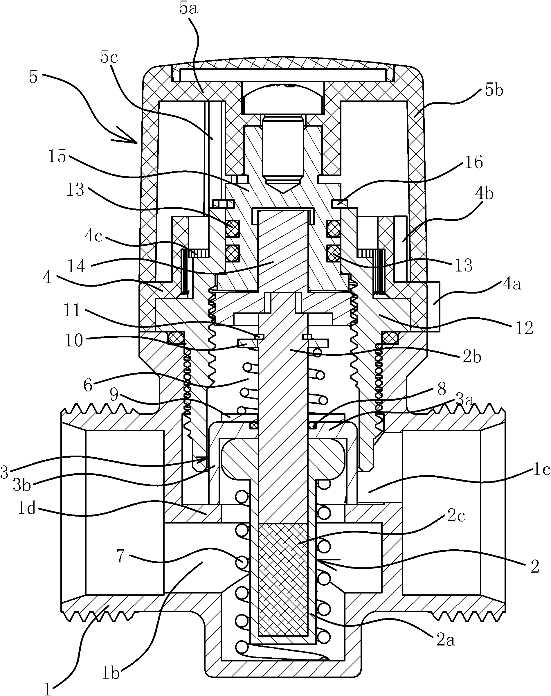
[0055] like Figure 5 As shown, the structure and principle of this embodiment are basically the same as those of Embodiment 1, the difference is that the valve core 3 is located in the water inlet chamber 1b and the valve core 3 is fixedly connected with the outer end of the ejector rod 2b of the temperature bulb 2 . The spool 3 is disc-shaped and the remaining push rods 2b are connected as a whole. A bottom cover 19 is fixedly connected to the side wall of the water inlet chamber 1b of the valve body 1, and a top cover 12 is fixedly connected to the side wall of the water outlet chamber 1c of the valve body 1. One end of the spring one 6 is in contact with the valve core 3, and the other end is in contact with the valve core 3. The top cover 12 leans against each other; one end of the spring 2 7 leans against the body 2 a of the temperature bulb 2 , and the other end leans against the bottom cover 19 .
[0056] The top cover 12 is provided with a lift screw 15 and a lift n...
PUM
 Abstract
Description
Claims
Application Information
 - R&D
- Intellectual Property
- Life Sciences
- Materials
- Tech Scout
- Unparalleled Data Quality
- Higher Quality Content
- 60% Fewer Hallucinations
Browse by: Latest US Patents, China's latest patents, Technical Efficacy Thesaurus, Application Domain, Technology Topic, Popular Technical Reports.
© 2025 PatSnap. All rights reserved.Legal|Privacy policy|Modern Slavery Act Transparency Statement|Sitemap|About US| Contact US: help@patsnap.com


