
Plane display structure and manufacturing method thereof

A technology of flat display and manufacturing method, applied in the field of flat display structure and its manufacturing, which can solve the problems of easy deformation of optical film and achieve the effect of increasing the strength of the overall structure

Inactive Publication Date: 2011-05-18
AU OPTRONICS CORP
View PDF7 Cites 36 Cited by
  • Summary
  • Abstract
  • Description
  • Claims
  • Application Information

AI Technical Summary

Problems solved by technology

However, the optical film arranged in a simple placement method often has the problem of easy deformation, and this problem will become more and more easily manifested under the trend of increasing size of liquid crystal display products, and the increasingly thinner liquid crystal display products are in the overall structure more fragile

Method used


Image

  • Plane display structure and manufacturing method thereof
  • Plane display structure and manufacturing method thereof
  • Plane display structure and manufacturing method thereof

Examples


Embodiment Construction

[0082] The invention provides a planar display structure and a manufacturing method thereof. In a preferred embodiment, the planar display structure and its manufacturing method of the present invention can be used in liquid crystal displays and their techniques. However, in other embodiments, the planar display structure and its manufacturing method of the present invention can be used in other types of displays and their processes.

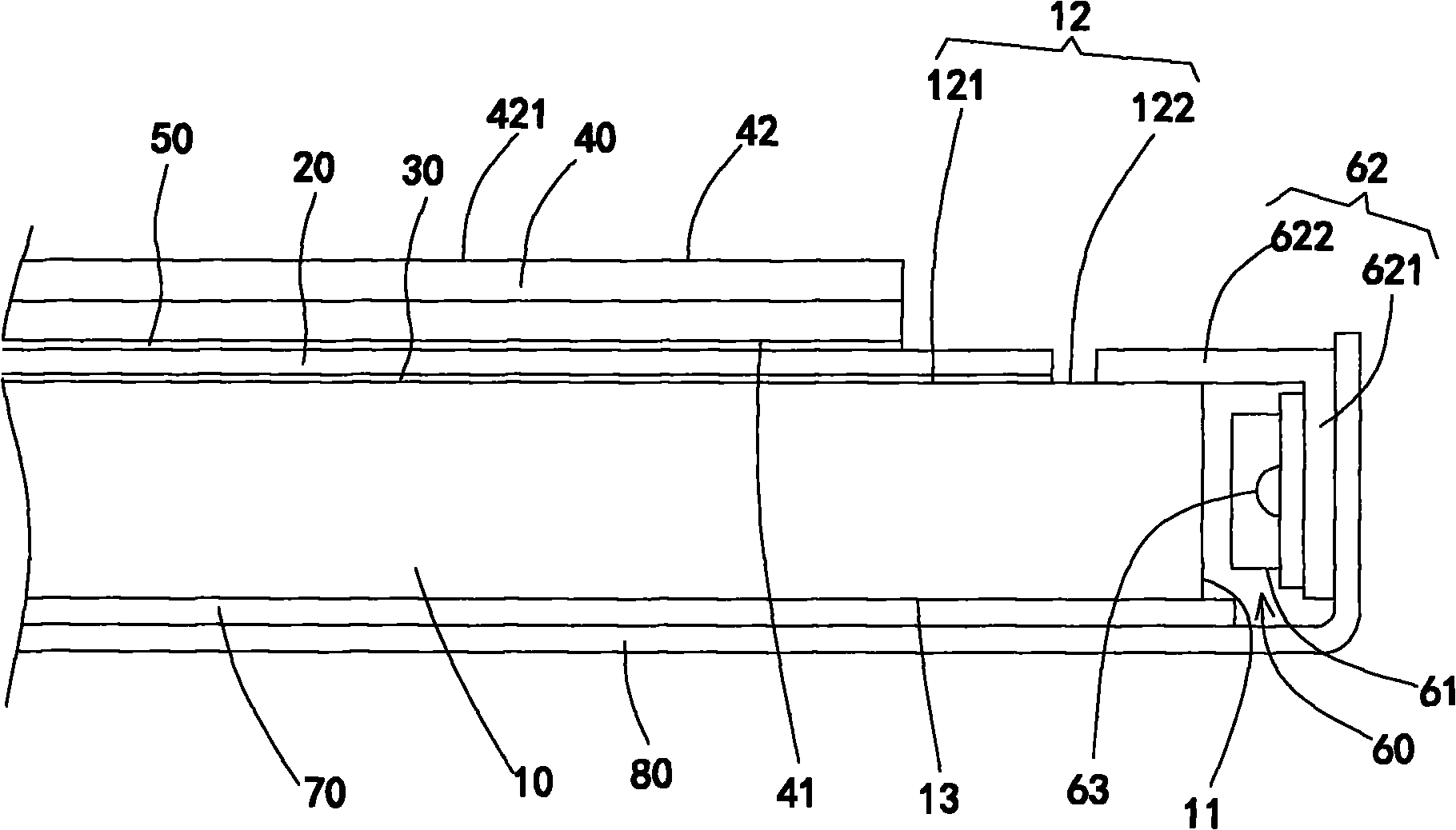
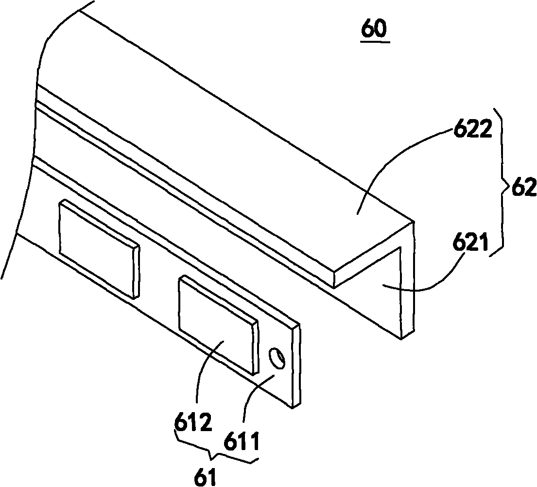
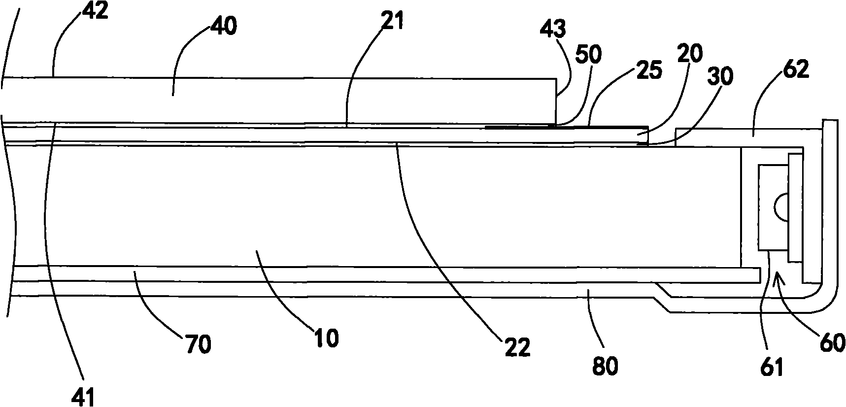
[0083] figure 1 It is a cross-sectional view of the first embodiment of the planar display structure of the present invention. like figure 1 As shown, the planar display structure includes a light guide plate 10 , an optical film 20 , a first adhesive layer 30 , a display panel 40 , a second adhesive layer 50 , a light emitting module 60 , a reflector 70 and a back plate 80 . The light guide plate 10 is an optical glass plate, and its material can be soda glass, silica glass, ultra clear glass or other types of optical glass. The light guide...


PUM


Abstract

The invention provides a plane display structure and manufacturing method thereof. The plane display structure comprises a light guide plate, an optical film, a first adhesive layer, a display panel, a second adhesive layer and a luminous module emitting light toward the light guide plate. The light guide plate is made from optical glass; the optical film is arranged on the light guide plate, and the optical film and the light guide plate are bonded through the first adhesive layer; the display panel is provided with a light incidence surface and a display surface opposite which are opposite to each other, wherein the light incidence surface is opposite to the optical film, and a display area is arranged at the middle part of the display surface; and the optical film and the display panel are bonded by the second adhesive layer to cover the light incidence surface including the projection range of the display area on the light incidence surface. The refractive indexes of the first adhesive layer and the second adhesive layer are both less than or equal to those of the light guide plate and the optical film. By utilizing the plane display structure and manufacturing method provided by the invention, the deformation of elements such as the optical film, the display panel and the like can be avoided so as to improve the entire structural strength.

Description

technical field [0001] The present invention relates to a flat display structure and a manufacturing method thereof; specifically, the present invention relates to a flat display structure with a display panel, an optical film and a light guide plate bonded to each other and a manufacturing method thereof. Background technique [0002] In the structure of the liquid crystal display, besides the display panel, the most important component is the backlight module. The use of the backlight module is because the liquid crystal molecules in the liquid crystal display do not emit light by themselves, but need to rely on the external light source provided by the backlight module to achieve its display function. The backlight module arranged behind the liquid crystal display panel is mainly composed of a light guide plate and a light-emitting element. The light emitted by the light-emitting element is transmitted to the liquid crystal display panel evenly through the conduction of t...

Claims


Application Information

Patent Timeline
IPC IPC(8): G02F1/13357G02F1/13G02F1/1333G02B6/00F21V13/00
Inventor 赖清坤陈晶川洪泓杰
Owner AU OPTRONICS CORP
Learn More