Supercharge Your Innovation With Domain-Expert AI Agents!

Protective device for solid electrolytic capacitor body

A technology of solid-state electrolysis and protection devices, which is applied in the direction of solid electrolytic capacitors, capacitor shells/packages, and capacitor parts, etc., and can solve problems such as easy damage to capacitor components, excessive size, and excessive packaging pressure

Active Publication Date: 2014-02-26
钰邦电子(无锡)有限公司
View PDF1 Cites 0 Cited by
  • Summary
  • Abstract
  • Description
  • Claims
  • Application Information

AI Technical Summary

Problems solved by technology

However, when encapsulating and covering the synthetic resin 14, the encapsulation pressure is still easy to damage the body of the capacitor assembly 6, causing short circuit and excessive leakage current. Therefore, how to improve the excessive encapsulation pressure problem in the prior art will be relevant. Issues that the industry needs to work on urgently

Method used


Image

  • Protective device for solid electrolytic capacitor body
  • Protective device for solid electrolytic capacitor body
  • Protective device for solid electrolytic capacitor body

Examples


Embodiment 1

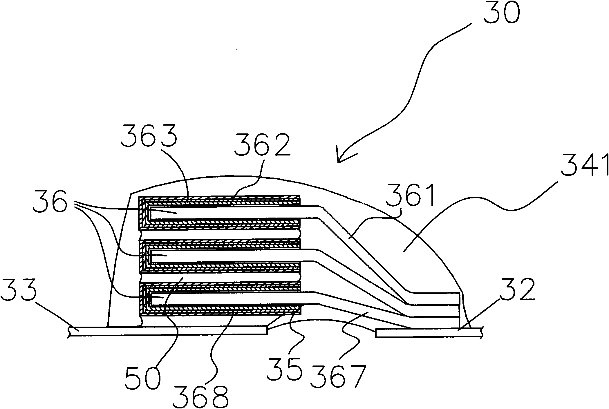
[0030] According to an embodiment of the present invention, a protection device for a solid electrolytic capacitor body is provided. Such as Figure 3-Figure 5 As shown, the present embodiment includes a solid electrolytic capacitor 30 . Among them, the solid electrolytic capacitor 30 includes a stacked multi-chip capacitor assembly 36, and the multi-chip capacitor assembly 36 is stacked on the anode terminal 32 and the cathode terminal 33; using packaging materials such as synthetic resin 34, the multi-chip The capacitor body composed of the capacitor assembly 36 , the anode terminal 32 and the cathode terminal 33 is packaged and fixed.

[0031] Among them, in the process of packaging and fixing, first, on the capacitor body composed of the multi-chip capacitor assembly 36, the anode terminal 32 and the cathode terminal 33, one or more layers of insulating glue and other packaging materials are applied. After drying and forming the airtight protective layer 341 (such as i...

Embodiment 2

[0035] Different from the above embodiment, in this embodiment, if Figure 6 and Figure 7 As shown, the solid electrolytic capacitor 30 includes a stacked multi-chip capacitor assembly 36, and the multi-chip capacitor assembly 36 is stacked on the anode terminal 32 and the cathode terminal 33; on the other side of the anode terminal 32 and the cathode terminal 33, parallel Another set of stacked multi-chip capacitor assemblies 36 is installed; the multi-chip capacitor assemblies 36, the anode terminal 32 and the cathode terminal 33 are packaged and fixed by using synthetic resin 34 through the encapsulation process to form another set of capacitor bodies.

[0036] Among them, in the process of encapsulating and fixing, at first, on the two groups of capacitor bodies formed by the multi-chip capacitor assembly 36, the anode terminal 32 and the cathode terminal 33, apply one or more layers of insulating glue, when the insulating glue dries After hard forming the airtight prote...


PUM


Abstract

The invention discloses a protective device for a solid electrolytic capacitor body. The protective device comprises a plurality of capacitor components which are arranged on an anode terminal and a cathode terminal in a laminated mode, wherein the plurality of capacitor components, the anode terminal and the cathode terminal are packaged and fixed by packaging materials such as synthetic resin and the like; and the packaging and fixing process comprises the following steps of: coating one or more layers of insulating glue on the capacitor body consisting of the plurality of capacitor components, the anode terminal and the cathode terminal to form an airtight protective layer; and packaging the capacitor body coated with the insulating glue by using the packaging materials. The protective device for the solid electrolytic capacitor body can overcome the defects that packaging pressure is high, the capacitor body is easy to damage, a short circuit and overhigh leakage current are easy to cause, and the like in the prior art, and has the advantages that: air tightness is high, the packaging pressure is low, the capacitor body is difficult to damage, and the short circuit and the overhigh leakage current are difficult to cause.

Description

technical field [0001] The present invention relates to the protection technology of capacitors, in particular to a protection device for a solid electrolytic capacitor body, in particular to a protection device that can reduce the pressure on the capacitor body when the packaging material is packaged, and avoid damage to the capacitor body due to excessive packaging pressure . Background technique [0002] In the existing technology, such as figure 1 and figure 2 As shown, the solid electrolytic capacitor 10 includes a multi-chip capacitor assembly 6 stacked in layers. At the bottom of the capacitor assembly 6 at the lowest level, an anode terminal 12 and a cathode terminal 13 are installed. The lower surface of the anode terminal 12 and the bottom surface of the cathode terminal 13 The bottom surface of the capacitor element 6 , the anode terminal 12 and the cathode terminal 13 are respectively covered with a synthetic resin 14 . [0003] Such as figure 2 As shown, i...

Claims


Application Information

Patent Timeline
Patent Type & Authority Patents(China)
IPC IPC(8): H01G9/08H01G9/15
Inventor 邱继皓黄文彦黄俊嘉林清封
Owner 钰邦电子(无锡)有限公司
Features
  • R&D
  • Intellectual Property
  • Life Sciences
  • Materials
  • Tech Scout
  • Unparalleled Data Quality
  • Higher Quality Content
  • 60% Fewer Hallucinations
Learn More