Turbomachine structural casing

A technology for structural frame and turbine, which is applied in gas turbine installations, mechanical equipment, engine manufacturing, etc., can solve problems such as complicated maintenance and operation of turbines, and achieve the effects of reducing size, improving metallurgical quality, and reducing costs.

Active Publication Date: 2011-05-18
SN DETUDE & DE CONSTR DE MOTEURS DAVIATION S N E C M A
View PDF10 Cites 10 Cited by
  • Summary
  • Abstract
  • Description
  • Claims
  • Application Information

AI Technical Summary

Problems solved by technology

Finally, the resulting frame forms a single piece that cannot be separated, thereby complicating the maintenance operations of the turbine

Method used


Image

  • Turbomachine structural casing
  • Turbomachine structural casing
  • Turbomachine structural casing

Examples


Embodiment Construction

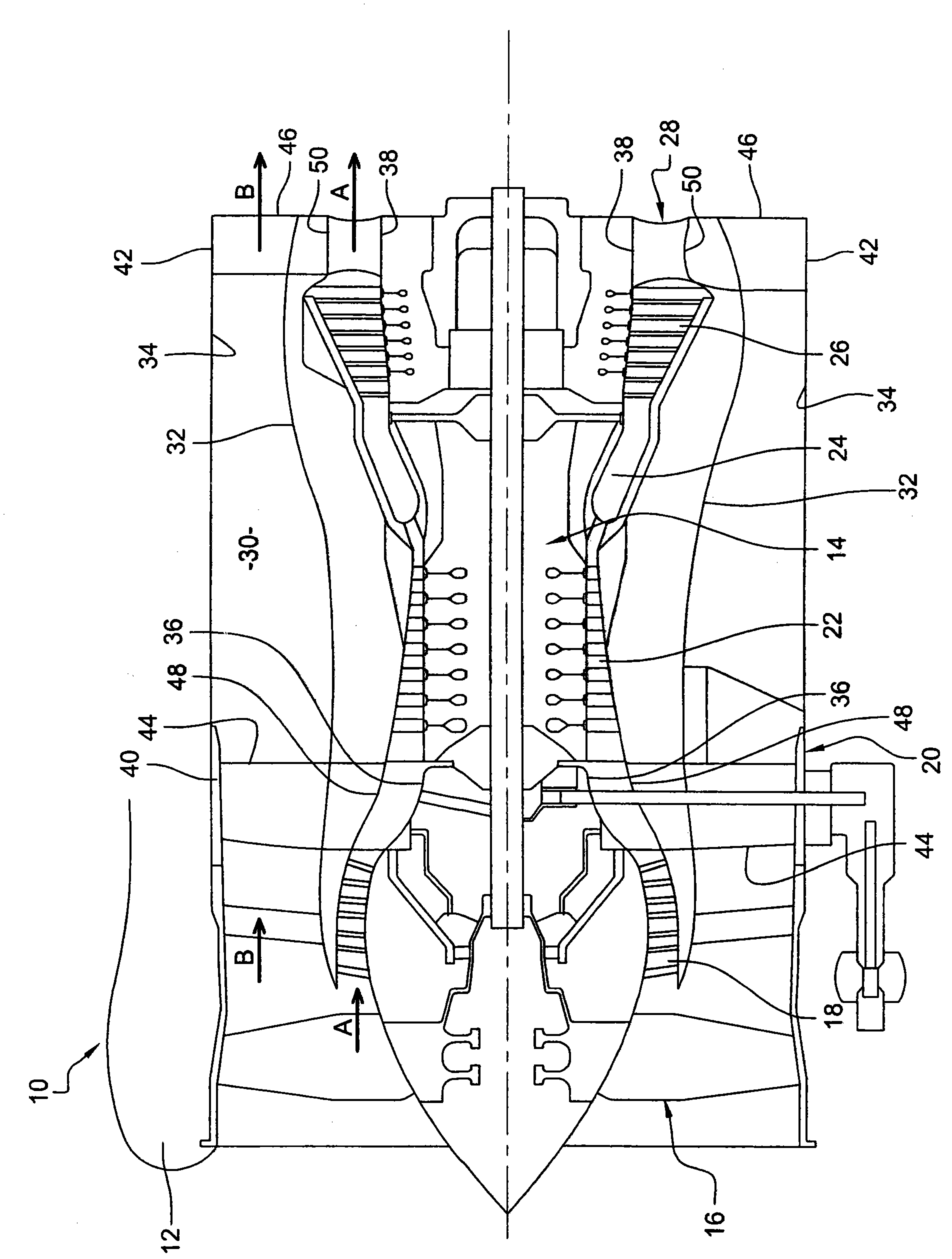
[0027] figure 1 Shown is a bypass turbine 10 comprising: a cylindrical cowl 12 surrounding a turbojet 14; and a fan wheel 16 mounted upstream of the turbojet 14, said turbojet from upstream to downstream mainly comprising: low pressure compression engine 18 , intermediate frame 20 , high pressure compressor 22 , combustor 24 , turbine 26 and discharge frame 28 .

[0028] In operation, the fan wheel 16 driven by the turbine 26 draws in an airflow which is divided into: the main airflow (arrow A) passing through the turbojet engine 14; A secondary airflow (arrow B) flowing aft of and around the engine 14 .

[0029] The fan duct 30 is formed from two coaxial generally cylindrical walls (an inner wall 32 and an outer wall 34 , respectively).

[0030] Intermediate frame 20 and discharge frame 28 are structural frames used to stiffen the turbine to limit deformation during operation. Both the intermediate frame 20 and the discharge frame 28 include pairs of coaxial rings, inner r...


PUM


Abstract

The present invention relates to a turbomachine structural casing (52), such as intermediate casing (52) or an exhaust casing (81, 87), formed of elements comprising at least two, one internal (60) and one external (62), coaxial shell rings and radial arms connecting the shell rings (60, 62), characterized in that at least one of these elements is formed of several parts bolted together.

Description

technical field [0001] The invention relates to a structural frame for a turbomachine, in particular such as a fan frame, an intermediate frame or an exhaust frame, but also a turbomachine comprising a frame of this type. Background technique [0002] In a turbomachine, such as an aircraft turbojet, a structural frame is arranged along the drive axis to stiffen the turbine in order to avoid deformation of the turbine and thereby better transmit impulses to the aircraft to which the turbine is fastened. Examples of such structural frames are intermediate frames and discharge frames. The intermediate frame is located between the low-pressure compressor and the high-pressure compressor, and the discharge frame is located downstream of the turbine section arranged at the outlet of the combustor. [0003] Frames of this type usually consist of at least two coaxial rings (an inner ring and an outer ring), the inner ring defining the inner side of the flow passage for the primary ...

Claims


Application Information

Patent Timeline
Patent Type & Authority Applications(China)
IPC IPC(8): F01D25/28F02C7/20F01D9/04
CPCY02T50/672F05B2230/60F05D2230/60F01D25/243F01D25/246F01D9/04Y02T50/60
Inventor 蒂里·弗朗索瓦·莫里斯·杜查特勒蒂里·乔治斯·保罗·帕潘多米尼克·罗林阿诺德·桑切斯
Owner SN DETUDE & DE CONSTR DE MOTEURS DAVIATION S N E C M A
Why Eureka
Try Eureka