Electromagnetic converter
An electromagnetic converter, magnetic flux technology, applied in the direction of sensors, electrical components, diaphragm structures, etc., can solve problems such as abnormal noise and poor performance, and achieve the effect of suppressing resonance, improving performance, and suppressing the generation of abnormal noise.
- Summary
- Abstract
- Description
- Claims
- Application Information
AI Technical Summary
Problems solved by technology
Method used
Image

Examples
Embodiment approach 1
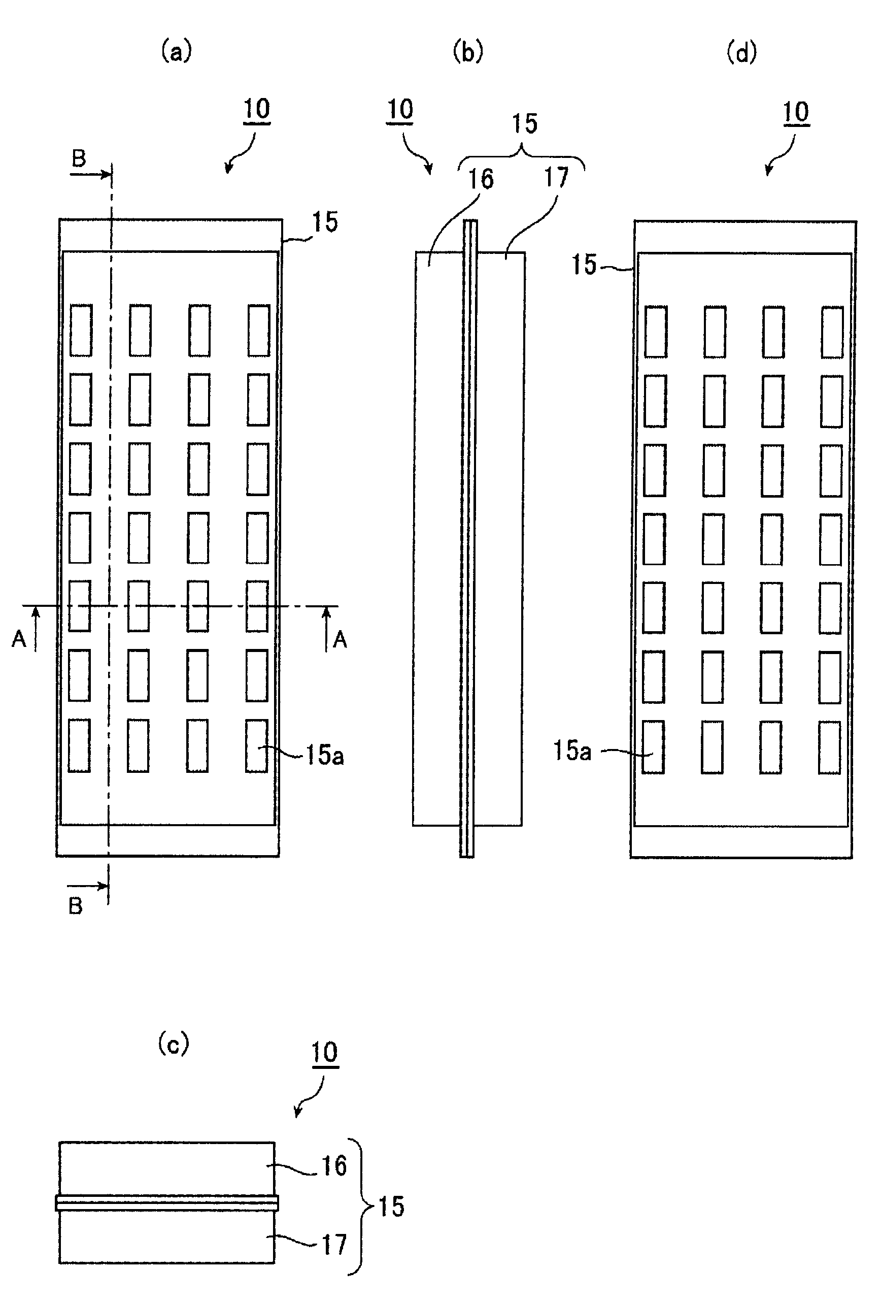
[0032] figure 1 Showing the appearance of electromagnetic transducer 10 according to Embodiment 1 of the present invention, figure 1 (a) is a front view showing the appearance of the electromagnetic transducer 10, figure 1 (b) is a side view showing the appearance of the electromagnetic converter 10 viewed from the long side, figure 1 (c) is a side view showing the appearance of the electromagnetic transducer 10 viewed from the short side, figure 1 (d) is a rear view showing the appearance of the electromagnetic converter 10 .
[0033] Such as figure 1 (a), figure 1 As shown in (d), in the electromagnetic transducer 10, the housing 15 has sound radiation holes 15a formed at regular intervals on both sides, as shown in figure 1 (b), figure 1 As shown in (c), the frame body 15 is configured by combining the upper side frame body 16 and the lower side frame body 17 . In addition, for the sake of explanation, a distinction is given between the upper frame body 16 and the lo...
Embodiment approach 2
[0063] In Embodiment 1, the structure in which a plurality of permanent magnets 32 and 33 are provided is described, but in Embodiment 2, the structure in which the size of the electromagnetic transducer 10 is miniaturized is used. Figure 8~Figure 13 Be explained. In addition, in order to avoid duplication of description, the same reference numerals are assigned to the same configurations as those in Embodiment 1, and description thereof will be omitted.
[0064] Figure 8 Showing the appearance of electromagnetic transducer 10 according to Embodiment 2 of the present invention, Figure 8 (a) is a front view showing the appearance of the electromagnetic transducer 10, Figure 8 (b) is a side view showing the appearance of the electromagnetic converter 10 viewed from the long side, Figure 8 (c) is a side view showing the appearance of the electromagnetic transducer 10 viewed from the short side, Figure 8 (d) is a rear view showing the appearance of the electromagnetic co...
PUM
 Abstract
Description
Claims
Application Information
 - R&D
- Intellectual Property
- Life Sciences
- Materials
- Tech Scout
- Unparalleled Data Quality
- Higher Quality Content
- 60% Fewer Hallucinations
Browse by: Latest US Patents, China's latest patents, Technical Efficacy Thesaurus, Application Domain, Technology Topic, Popular Technical Reports.
© 2025 PatSnap. All rights reserved.Legal|Privacy policy|Modern Slavery Act Transparency Statement|Sitemap|About US| Contact US: help@patsnap.com