Hobbing type cross-cutting shear

A cross-cutting and rolling-cutting technology, applied in the field of sheet metal shearing machines, can solve problems such as reduced shearing efficiency, unfavorable equipment strength, and influence on adjustment accuracy, so as to reduce equipment cost and energy consumption, and reduce design workload , Improve the effect of adjustment accuracy

Inactive Publication Date: 2011-05-25
张恒昌
View PDF6 Cites 19 Cited by
  • Summary
  • Abstract
  • Description
  • Claims
  • Application Information

AI Technical Summary

Problems solved by technology

[0002] At present, the roll-cut cross-cutting shears used for sheet metal shearing at home and abroad have mechanical transmission, that is, crankshaft-connecting rod transmission and hydraulic transmission, that is, through push rod-connecting rod transmission, with dual-axis and double eccentricity. and single-axis double-eccentric, they all have the following disadvantages: ① double-axis double-eccentric and single-axis double-eccentric rolling shears, the shearing mechanism belongs to the crank-link mechanism, from the analysis of the principle of motion, this transmission It is impossible to practice pure rolling shear in the form, and there is a rolling error
②The main transmission system of the hobbing cut directly bears the shear force, and the shear force is proportional to the square of the thickness of the plate, which will cause the power parameters of the main drive, motor power, equipment weight, and equipment investment to increase with the increase of the plate thickness. Large and sharp increase, when the thickness of the plate increases to a certain extent, the equipment will not be able to meet the requirements of rolling cutting, which greatly limits the production capacity of the shearing machine
③Because the rolling cutting of the upper shearing edge and the overl...

Method used


Image

  • Hobbing type cross-cutting shear
  • Hobbing type cross-cutting shear
  • Hobbing type cross-cutting shear

Examples


Embodiment Construction

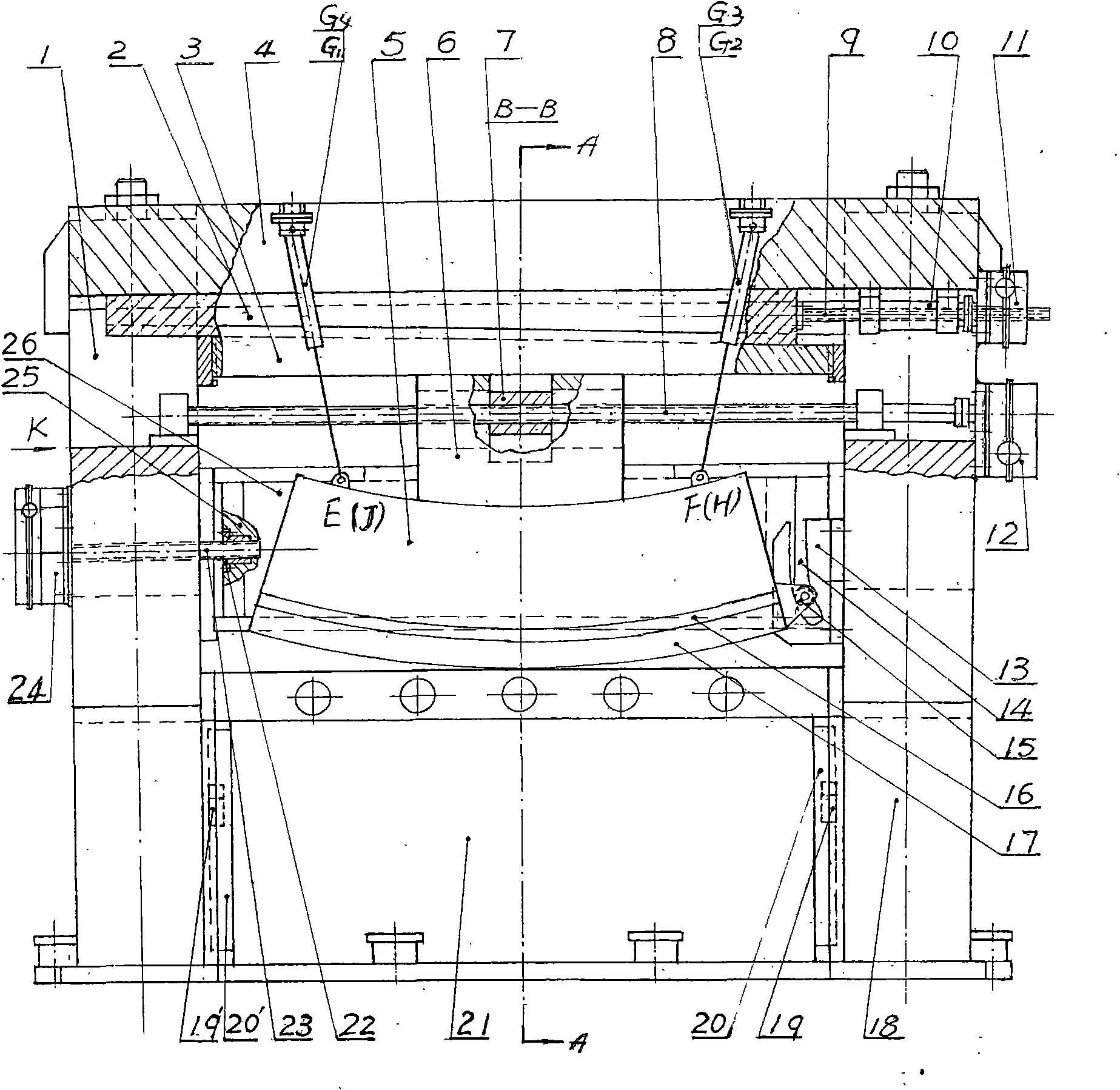
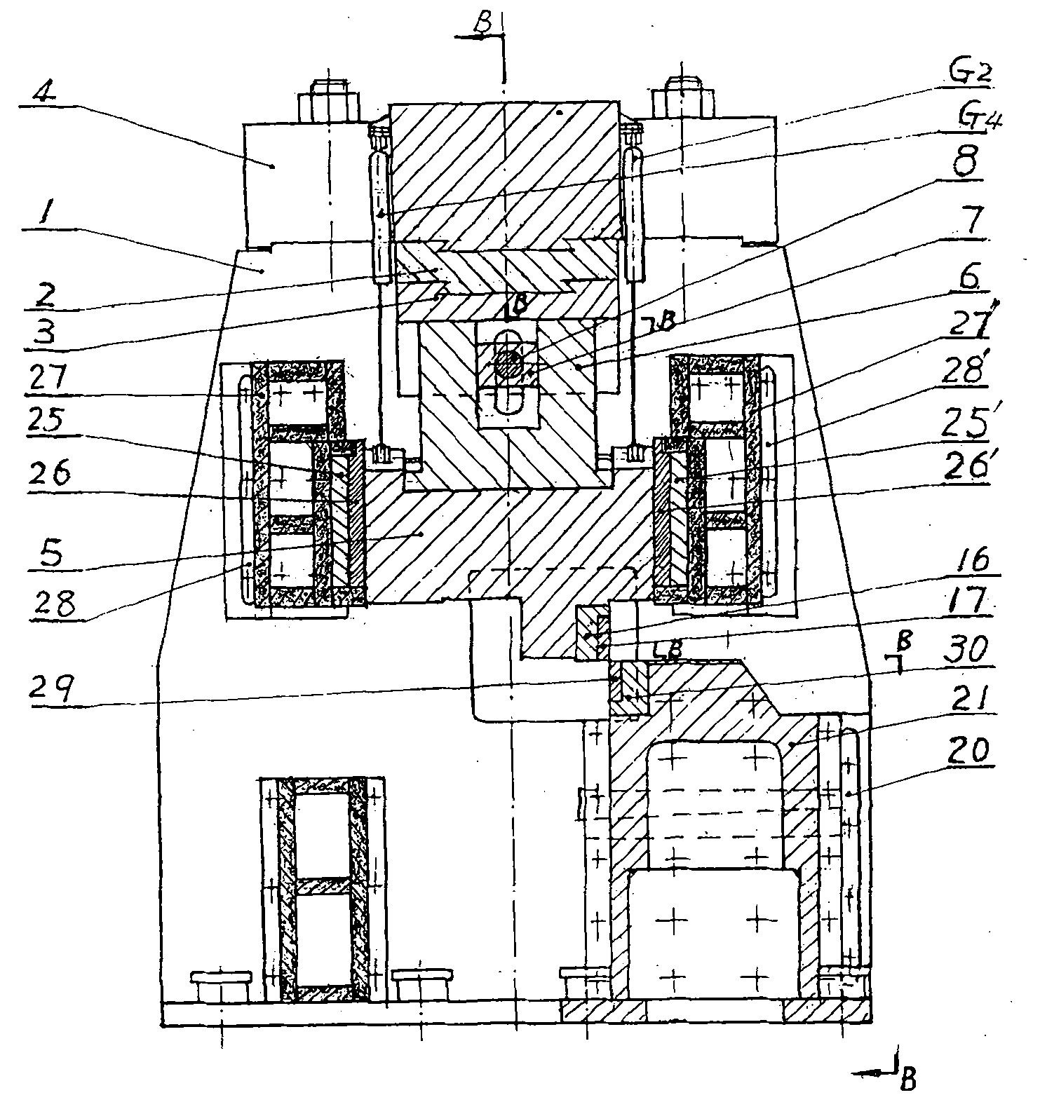
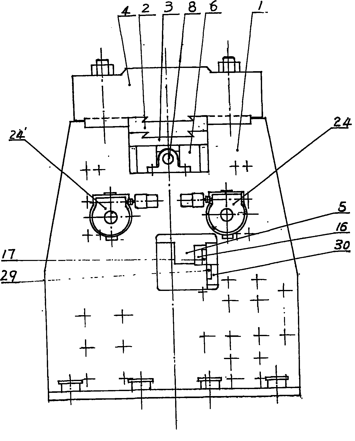
[0043] (1) The upper cutting edge is used for pure rolling shear: such as figure 1As shown, when the transmission box 12 drives the ball screw 8 to rotate, the ball nut 7 drives the arcuate sliding seat 6 to move left or right, and the arcuate sliding seat 6 forces the upper knife by contacting the arc surface of the upper knife rest 5 Frame 5 makes pure rolling shear under the restriction of roller 15 and guide groove 14 together with upper cutting edge 17 .

[0044] (2) The lifting adjustment of the upper cutting edge: such as figure 1 As shown, when the transmission box 11 drives the ball nut 10 to rotate, the matched ball screw 9 drives the upper wedge 2 to move horizontally, and through the contact of the two wedges with the inclined surface and the action of the balance hydraulic cylinder, the lower wedge 3 is forced to The arc slide seat 6, the upper knife rest 5 and the upper cutting edge 17 move upwards or downwards to realize the adjustment of the overlapping amount...


PUM


Abstract

The invention relates to a hobbing type cross-cutting shear which belongs to the technical field of shearing machines for metal plates, comprises a closed frame comprising a left frame, a right frame, an upper crossbeam and a lower knife rest, an upper shear blade lifting mechanism, an arc surface sliding seat type hopping mechanism, a roll wheel-guide groove type guide mechanism, a hydraulic cylinder balancing mechanism, a shearing blade clearance adjusting mechanism and a mechanism for connecting an upper knife box and an upper knife rest, and is characterized in that the lifting of an upper shear blade is realized by the movement of upper and lower oblique wedges mounted on the lower surface of the upper crossbeam and the action of balancing a hydraulic cylinder. The pure rolling shearing of the upper shear blade is realized by the transverse movement of an arc surface sliding seat mounted on the lower surface of the lower oblique wedge and the constraint of the roll wheel-guide groove mechanism. The adjustment of the clearance between the shear blades is realized by the movement of the oblique wedges arranged before and after the upper knife rest. The hobbing type cross-cutting shear has the advantages that a rolling ball spiral mechanism is adopted for driving the oblique wedges to move, thereby greatly improving the carrying capacity of equipment. The arc surface slidingseat type mechanism and the roll wheel-guide groove type guide mechanism are adopted, thereby being capable of realizing the pure rolling shearing.

Description

Technical field: [0001] The invention belongs to the technical field of sheet metal shears, and in particular relates to a roll-cut cross-cut shear for cutting sheet metal. Background technique: [0002] At present, the roll-cut cross-cutting shears used for sheet metal shearing at home and abroad have mechanical transmission, that is, crankshaft-connecting rod transmission and hydraulic transmission, that is, through push rod-connecting rod transmission, with dual-axis and double eccentricity. and single-axis double-eccentric, they all have the following disadvantages: ① double-axis double-eccentric and single-axis double-eccentric rolling shears, the shearing mechanism belongs to the crank-link mechanism, from the analysis of the principle of motion, this transmission It is impossible to practice pure rolling shear in the form, and there is a rolling error. ②The main transmission system of the hobbing cut directly bears the shear force, and the shear force is proportional...

Claims


Application Information

Patent Timeline
IPC IPC(8): B23D15/08B23D15/12B23D33/00
Inventor 张恒昌张坤
Owner 张恒昌
Why Eureka
Try Eureka