Sliding-type tool special for positioning clamp screw hole

A technology for locating wire clips and special tools, applied in manufacturing tools, workshop equipment, etc., can solve problems such as the deviation between the marked position and the actual position of the screw hole, the template cannot be directly fixed on the wire clip, and the template cannot be reused many times. Improve work efficiency, avoid reprocessing, and save resources

Active Publication Date: 2011-05-25
STATE GRID SHANDONG ELECTRIC POWER +1
View PDF6 Cites 29 Cited by
  • Summary
  • Abstract
  • Description
  • Claims
  • Application Information

AI Technical Summary

Problems solved by technology

The use of paper stencils has the following two defects: 1. The stencil cannot be directly fixed on the wire clip, and the stencil is often accidentally touched during work, resulting in a deviation between the marked position and the actual position of the screw hole; 2. The stencil cannot be reused many times. After the first use, the positioning hole on the drawing will become larger, which will affect the positioning accuracy

Method used


Image

  • Sliding-type tool special for positioning clamp screw hole
  • Sliding-type tool special for positioning clamp screw hole
  • Sliding-type tool special for positioning clamp screw hole

Examples


Embodiment Construction

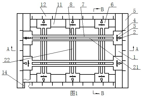
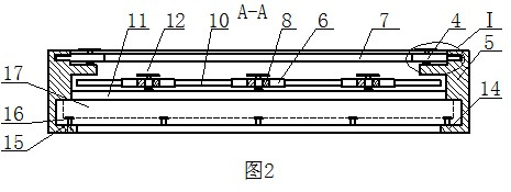
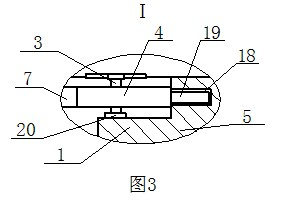
[0009] The special tool for the position of the screw hole of the sliding type positioning wire clamp according to the present invention includes a frame, such as figure 1 As shown, the frame is a square frame composed of two horizontal scales 12 up and down and two vertical scales 5 on the left and right. The surfaces of the vertical scales 5 and the horizontal scales 12 are all provided with scale marks 13, and the inner sides of each horizontal scale 12 A transverse movement chute 10 is provided, and a vertical movement chute 18 is provided on the inner side of each longitudinal scale 5; a transverse movement caliper 8 is installed between the two transverse scales 12, and a second through groove 22 is provided on the transverse movement caliper 8. The two ends of the moving caliper 8 are respectively provided with a traverse slider 6, and the two traverse sliders 6 are provided with a traverse guide block 9, and the two traverse guide blocks 9 are respectively connected wit...


PUM


Abstract

The invention discloses a sliding-type tool special for positioning a clamp screw hole. The tool comprises a framework, wherein the framework is a square frame which is formed by connecting two transverse staff gauges and two longitudinal staff gauges; the surfaces of both of the longitudinal staff gauges and the transverse staff gauges are provided with scale marks; a transverse sliding chute is reserved inside both of the transverse staff gauges; a vertical sliding chute is reserved inside both of the longitudinal staff gauges; a transverse caliper is arranged between the two transverse staff gauges; a second through slot is reserved on the transverse caliper; a transverse sliding block is respectively arranged at the two ends of the transverse caliper; a transverse guide block is respectively arranged on the two transverse sliding blocks; the two transverse guide blocks are respectively matched with the two transverse sliding chutes; a vertical caliper is arranged between the two longitudinal vertical staff gauges; a first through slot is reserved on the vertical caliper; a vertical sliding block is respectively arranged at the two ends of the vertical caliper; a vertical guide block is arranged on each vertical sliding block; the two vertical guide blocks are respectively matched with the two vertical sliding chutes; and both the vertical sliding blocks and the transverse sliding blocks are provided with scale mark pointers.

Description

technical field [0001] The invention relates to a sliding type special tool for locating screw hole positions of wire clamps. Background technique [0002] At present, in the electric power sector, the processing of wire clips refers to locating the position of the screw holes on the wire clips according to the template instructions, and then using a bench drill to drill out the screw holes. The existing processing template of the wire clip adopts a paper template, and the specific operation is as follows: when processing the wire clip, first draw the template, mark the position of the screw hole, then place the template on the wire clip, and use a gun to mark the wire clip , and finally fix the clamp on the bench drill, and drill the screw holes according to the marks made. The use of paper templates has the following two defects: 1. The template cannot be directly fixed on the wire clip, and the situation of accidentally touching the template often occurs during work, re...

Claims


Application Information

Patent Timeline
Patent Type & Authority Applications(China)
IPC IPC(8): B25H7/04
Inventor 刘洪正顾显华刘矞肖辉菅有为刘况张文佳曹阳刘宝坤吕婷婷
Owner STATE GRID SHANDONG ELECTRIC POWER
Why Eureka
Try Eureka