
High-speed shearing, homogenizing and emulsifying device

A technology of high-speed shearing and homogeneous emulsification, which is applied to mixers with rotating stirring devices, transportation and packaging, chemical instruments and methods, etc., can solve problems such as viscous damage, troublesome use, poor adjustment effect of emulsifiers, etc., to achieve Viscosity reduction effect

Active Publication Date: 2020-09-11
浙江巨邦高新技术有限公司
View PDF13 Cites 5 Cited by
  • Summary
  • Abstract
  • Description
  • Claims
  • Application Information

AI Technical Summary

Problems solved by technology

[0003] The currently used emulsification device needs to adjust the gap between the rotor and the stator when adjusting the emulsification effect. Since the position between the rotor and the stator is relatively fixed, it is necessary to replace the gap between the rotor and the stator when adjusting the emulsification effect. The stator or rotor of the emulsifier makes the adjustment effect of the emulsifier worse, and in the process of using the existing emulsifier, the material will directly enter the gap between the rotor and the stator. For some hard granular materials During the emulsification process, the emulsification effect is poor, and it is easy to cause damage to the stator and rotor, and when emulsifying some high-viscosity materials, the mixing effect is poor, and high-viscosity materials need to be sheared at high speed in advance before emulsification , to destroy the stickiness, it is troublesome to use
[0004] Moreover, the emulsification device currently used needs to be placed in the material bucket, so that some emulsified materials will be emulsified repeatedly, making the emulsification efficiency lower, and even some unemulsified phenomena will appear.

Method used


Image

  • High-speed shearing, homogenizing and emulsifying device
  • High-speed shearing, homogenizing and emulsifying device
  • High-speed shearing, homogenizing and emulsifying device

Examples


Embodiment Construction

[0020] The following will clearly and completely describe the technical solutions in the embodiments of the present invention with reference to the accompanying drawings in the embodiments of the present invention. Obviously, the described embodiments are only some, not all, embodiments of the present invention. Based on the embodiments of the present invention, all other embodiments obtained by persons of ordinary skill in the art without making creative efforts belong to the protection scope of the present invention.

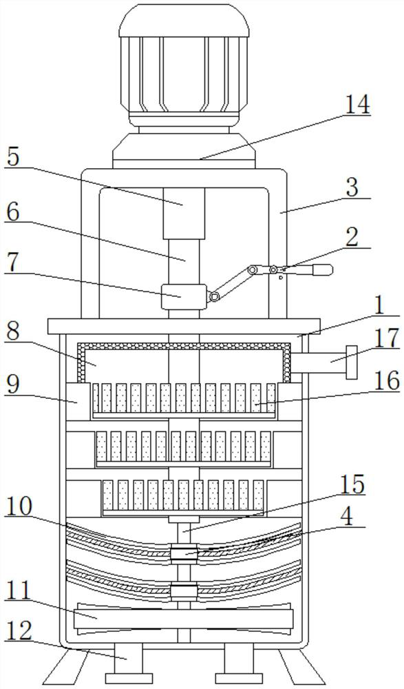
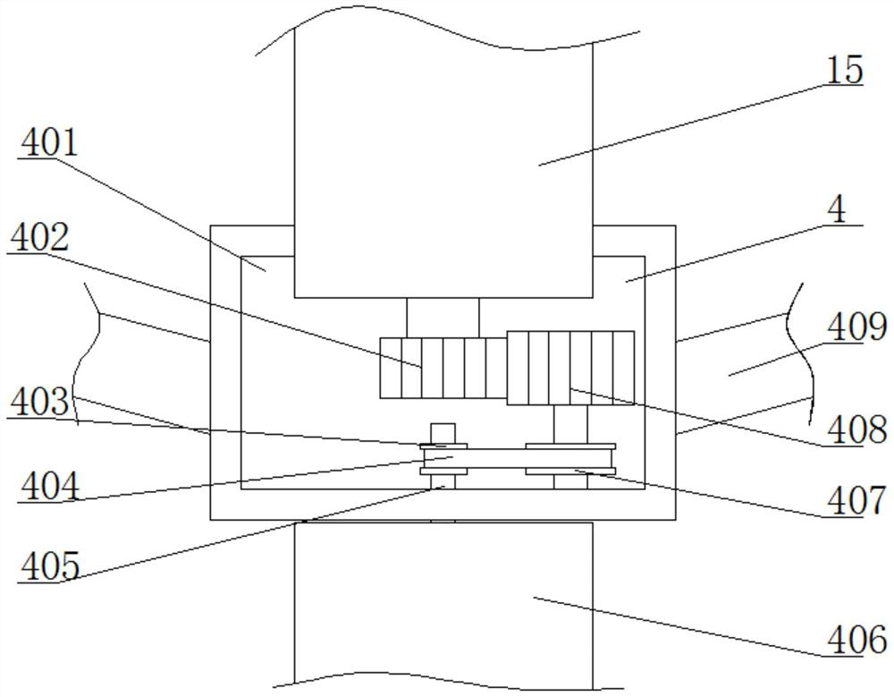
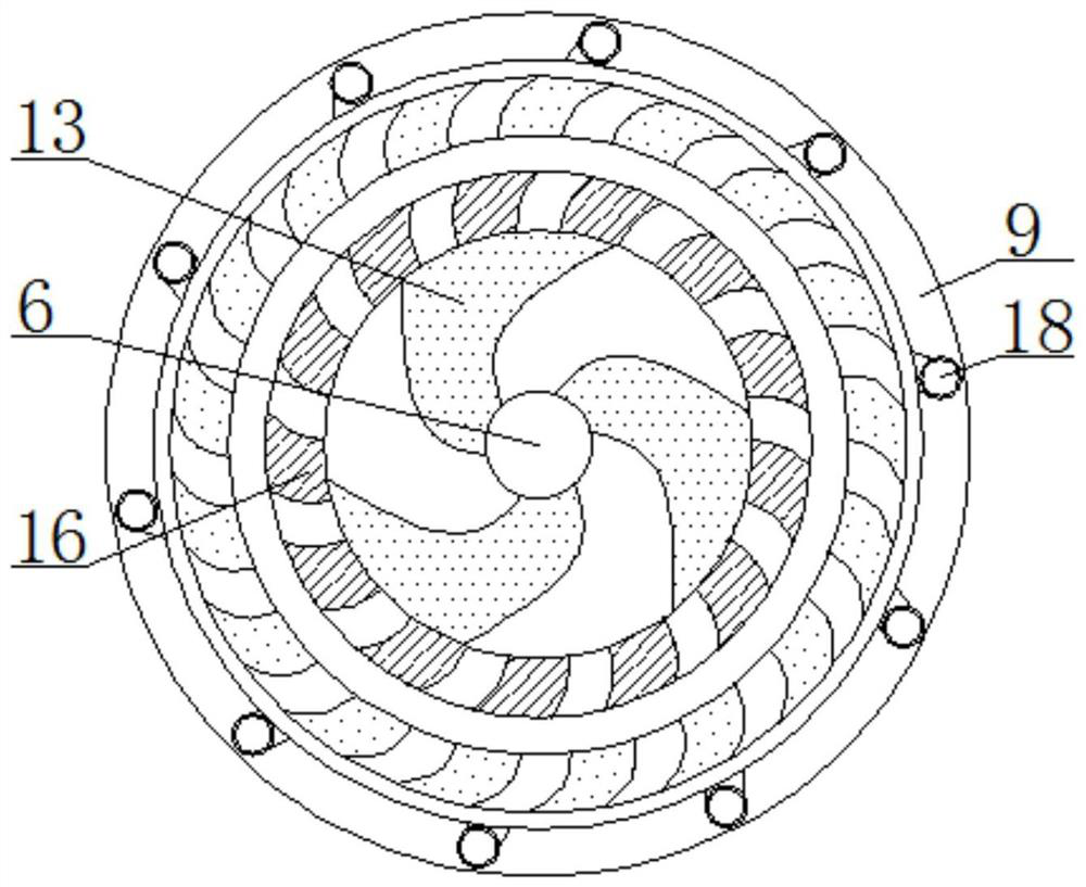
[0021] see Figure 1-4 , a high-speed shearing homogeneous emulsification device, including an external cylinder 1, a support base 3 is fixedly installed on the top of the external cylinder 1, a high-speed motor 14 is fixedly installed on the top of the support base 3, and the output end of the high-speed motor 14 extends to the support base The inside of 3 is fixedly connected with a hollow connecting shaft 5, the bottom of the hollow connecting shaft 5 is mo...


PUM


Abstract

The invention relates to the technical field of emulsifying equipment, and discloses a high-speed shearing, homogenizing and emulsifying device. The device includes an outer cartridge, a supporting seat is fixedly mounted at the top of the outer cylinder, a high-speed motor is fixedly mounted at the top of the supporting seat, and the output end of the high-speed motor extends into the supportingbase and is fixedly connected to a hollow connecting shaft, a rotating shaft is movably clamped to the bottom of the hollow connecting shaft, a lifting apparatus is movably installed on the outer surface of the rotating shaft, the bottom of the rotating shaft extends into the outer cylinder, and the outer surface of the rotating shaft is fixedly sleeved with rotors. When the high-speed shearing, homogenizing and emulsifying device is used, the situation that a traditional emulsifying machine needs to be placed in a charging barrel, so that materials in the charging barrel flow into the emulsifying device disorderly is changed, repeated processing of the materials by the emulsifying device is prevented, with the device, materials can be fed and emulsified orderly and then flow out, and theemulsifying efficiency is improved.

Description

technical field [0001] The invention relates to the technical field of emulsification equipment, in particular to a high-speed shear homogeneous emulsification device. Background technique [0002] The emulsifier shears, disperses and impacts the materials through the high-speed rotation of the homogenizing head connected to the engine, so that the materials will become more delicate and promote the blending of oil and water. It is widely used in cosmetics, shower gels, sunscreens, etc. , Many cream products need to use emulsifiers, sauces, juices, etc. in the food industry, ointments, petrochemicals, paints, coatings, inks, etc. in the pharmaceutical industry will use emulsifiers. [0003] The currently used emulsification device needs to adjust the gap between the rotor and the stator when adjusting the emulsification effect. Since the position between the rotor and the stator is relatively fixed, it is necessary to replace the gap between the rotor and the stator when adj...

Claims


Application Information

Patent Timeline
Patent Type & Authority Applications(China)
IPC IPC(8): B01F7/16B01F7/24B01F13/10B01F3/08
CPCB01F23/41B01F27/812B01F27/92B01F33/8305
Inventor 张曼玲
Owner 浙江巨邦高新技术有限公司
Learn More