Feeding mechanism of sewing machine

A feeding mechanism and sewing machine technology, applied in the field of sewing machines, can solve problems such as cumbersome processing, high labor costs, and low production efficiency, and achieve the effects of avoiding reprocessing procedures, reducing labor costs, and reducing work intensity

Active Publication Date: 2015-10-28
程林森
View PDF6 Cites 5 Cited by
  • Summary
  • Abstract
  • Description
  • Claims
  • Application Information

AI Technical Summary

Problems solved by technology

[0002] Existing sewing machines include disc sewing machines and clamping machines. Each model of the sewing disc of the disc sewing machine corresponds to a specific stitch distance, and the feeding process is Manually thread two layers of fabrics on the hanging needles of the sewing tray one after another, and then need the staff to step on the pedal switch to complete the subsequent sewing. This process has high requirements for the proficiency of the staff, because the hanging needles are very Dense each stitch needs to be accurately inserted into the corresponding coil of the fabric. It is difficult f

Method used


Image

  • Feeding mechanism of sewing machine
  • Feeding mechanism of sewing machine
  • Feeding mechanism of sewing machine

Examples


Embodiment Construction

[0025] The solution of the present invention will be described in detail below in conjunction with the accompanying drawings.

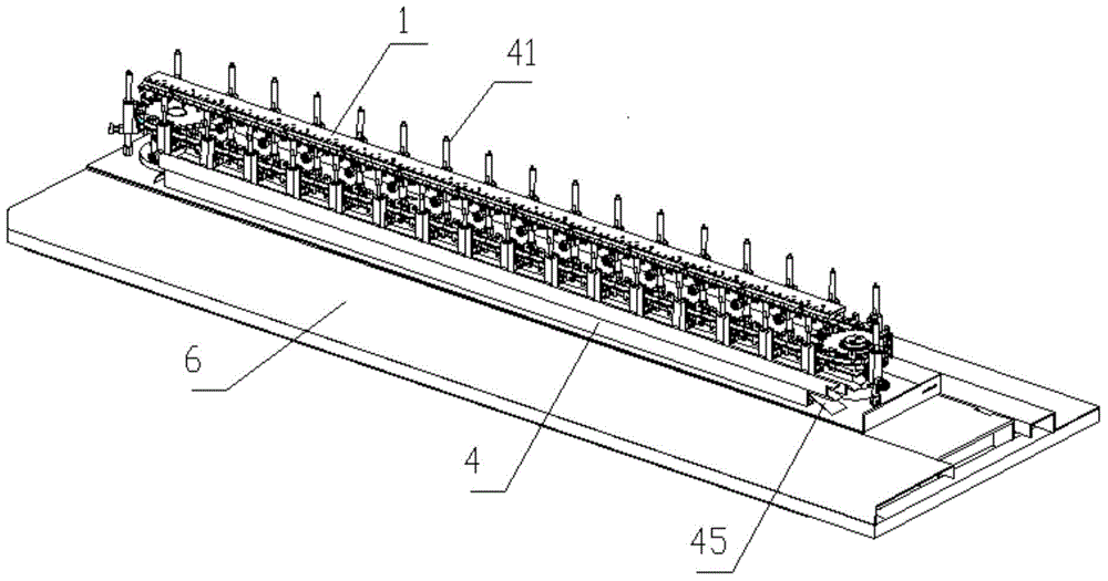
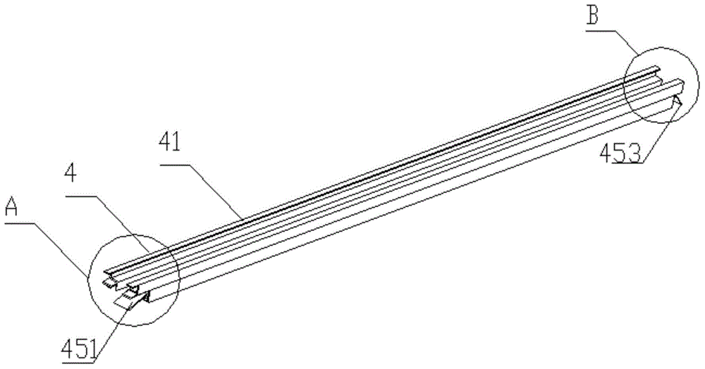
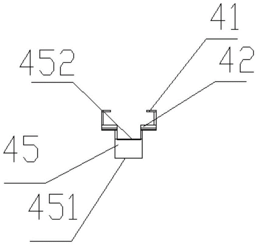
[0026] Such as figure 1 , the feeding mechanism of the sewing machine provided by the present embodiment is located on the frame, and mainly consists of frame 1, hanging cloth plate 5, transmission belt 31, limit rail 452, ramp 45, some ejector rods 2, thimble 22 And two driving rollers 3. The transmission rollers 3 are rotatably connected to the frame 1, and the two transmission rollers 3 are connected by a transmission belt 31 to form a closed-loop transmission chain. The ejector rods 2 are evenly arranged on the transmission belt 31 and move with the transmission belt 31 in a set motion track. The trajectory is determined by figure 1 It can be known as a type of ellipse, which is composed of two straight transmission paths and two semi-circular transmission paths. The high ends of the limiting rails are respectively connected with the two ramps...


PUM


Abstract

The invention relates to a feeding mechanism of a sewing machine. The feeding mechanism comprises a rack, a cloth hanging plate, a driving belt, a limiting rail, ramps, a plurality of thimbles and two driving roller wheels. The two driving roller wheels are rotatably connected with the rack and are connected in a transmission manner through the driving belt. The limiting rail and a high end, and the ramps connected with two ends of the limiting rail, are arranged on a side of a close-loop transmission chain. The plurality of thimbles respectively slide up and down and are elastically arranged on the driving belt. The cloth hanging plate is provided with a spliced eye, and the cloth hanging plate is arranged above the driving belt. Beneficial effects are that the cloth hanging plate which is provided with cloth can be directly driven to do rectilinear motion to feed. Compared with a fell seam machine, the feeding mechanism prevents manual feeding, and positions of cloth hung on cloth hanging needles are relatively fixed, and a water gap can be controlled, and the front end and the rear end of the cloth can be effectively sewed, and a reprocessing program is prevented.

Description

technical field [0001] The invention relates to a sewing machine, in particular to a feeding mechanism of the sewing machine. Background technique [0002] The existing sewing machine includes a sewing machine and a clamping machine. Each model of the sewing machine of the sewing machine corresponds to a specific stitch distance. On the cloth needle, the staff needs to step on the pedal switch to complete the subsequent stitching. This process has high requirements for the proficiency of the staff. Since the cloth hanging needles are very dense, each needle needs to be accurately inserted into the corresponding coil of the fabric. It is difficult for personnel to maintain a high work efficiency. The whole process is completely dependent on manual operation. The labor cost of the factory is high and the production efficiency is low; while the clamping machine requires workers to manually clamp the cloth with a cloth support, and then the worker quickly clamps the cloth. Dra...

Claims


Application Information

Patent Timeline
IPC IPC(8): D05B33/00D05B27/00
Inventor 马恒喜张海蒋继章邹欣程林森程志兰张网喜卞文武卞学峰李普江周静
Owner 程林森
Why Eureka
Try Eureka