Decompression discharge pipe and raw material mixing system adopting the same

A batching system and feeding pipe technology, which is applied in the direction of conveying bulk materials, conveyors, transportation and packaging, etc., can solve the problems of raw material weighing errors, the inlet valve body of the mixing tank can not be completely sealed, leakage, etc.

Inactive Publication Date: 2013-05-08
CHONGQING POLYCOMP INT
View PDF1 Cites 0 Cited by
  • Summary
  • Abstract
  • Description
  • Claims
  • Application Information

AI Technical Summary

Problems solved by technology

[0005] In order to solve the above-mentioned problem that the valve body of the inlet valve of the mixing tank cannot be completely sealed due to the wear of the sealing ring, the compressed air in the mixing tank leaks upward from the inlet valve of the mixing tank under pressure during the production process, forming a The upward air pressure causes the problem of raw material weighing error. The present invention provides a pressure relief type feeding tube, which can eliminate the above-mentioned raw material weighing error

Method used


Image

  • Decompression discharge pipe and raw material mixing system adopting the same
  • Decompression discharge pipe and raw material mixing system adopting the same
  • Decompression discharge pipe and raw material mixing system adopting the same

Examples


Embodiment 1

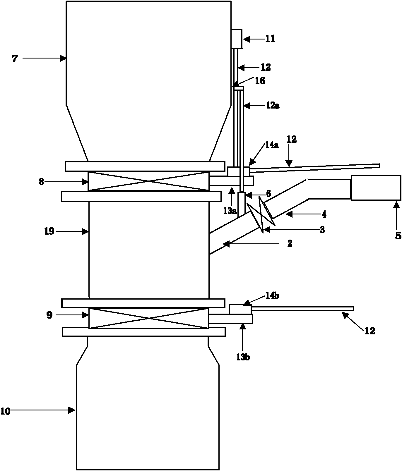
[0025] figure 1 It is a specific embodiment of a pressure relief type feed pipe. Among the figure, the large-scale outlet valve 8 and the mixing tank inlet valve 9 are respectively connected with the upper and lower parts of the feeding pipe body 19 with screws, and the feeding pipe body 19 is a cylinder or a square cylinder. An oblique upward pressure relief pipe 2 is installed on the side of the pipe body 19, and is welded and fixed at an angle of 45° with the blanking pipe body 19. A non-return air pipe 6 with an inner diameter of 10 mm is vertically installed on the pressure relief pipe 2 upper side at a distance of 200 mm from the discharge pipe body 19 along the pressure relief pipe 2 direction. The upper end of the pressure relief pipe 2 is connected to one end of a closed valve 3, and the other end of the closed valve 3 is connected to a transparent hose 4 with a length of 2 meters and a diameter of 60 mm. The transparent hose 4 is supported by an auxiliary bracket ne...

Embodiment 2

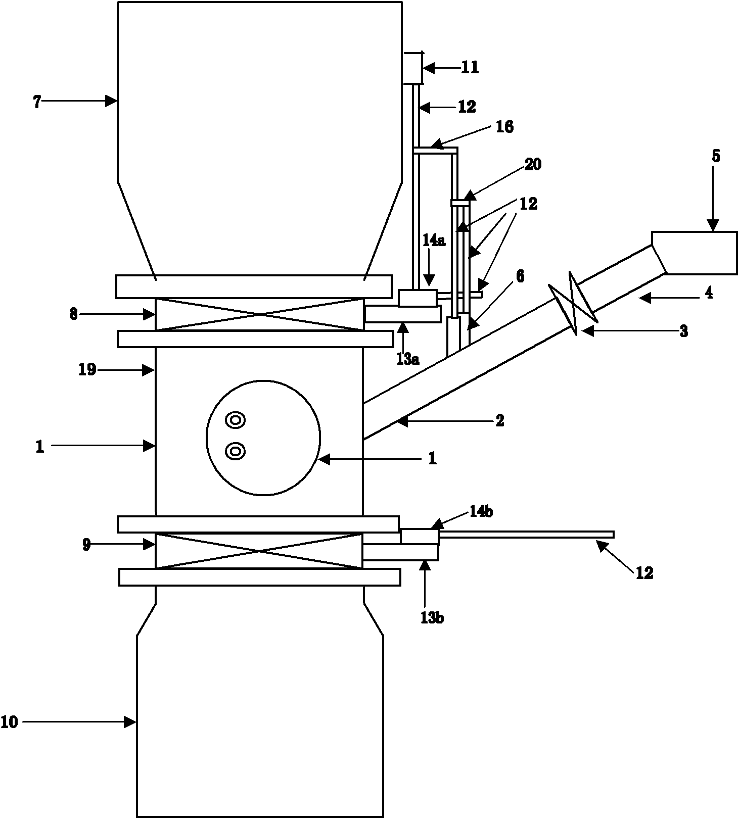
[0032] figure 2 It is a specific embodiment of the second pressure relief type feeding pipe. In the figure, the large scale outlet valve 8 and the mixing tank inlet valve 9 are respectively connected with the feeding pipe body 19 with screws, and the feeding pipe body 19 is a cylinder Body or square cylinder, a circular openable observation hole 1 with a diameter of 250 mm to 400 mm is set on the feeding pipe body 19 . An oblique upward pressure relief pipe 2 is installed on the blanking tube body 19 next to the observation hole 1, and is welded and fixed with the blanking tube body 19 at an angle of 30°. On the pressure relief pipe 2 upper side, along the direction of the pressure relief pipe 2, two check pipes 6 with an inner diameter of 5mm are installed in parallel at a distance of 200mm from the blanking pipe body 19 at a distance of 50mm. The upper end of the pressure relief pipe 2 is connected to one end of a closed valve 3, and the other end of the closed valve 3 is ...

Embodiment 3

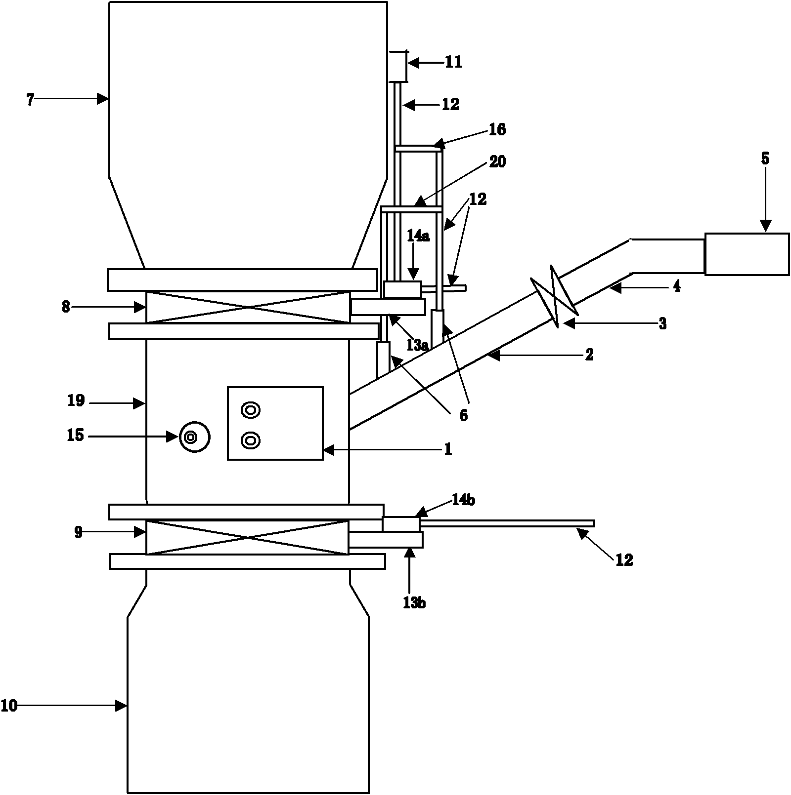
[0038] image 3 It is a specific embodiment of the third pressure relief type feeding pipe. In the figure, the large scale outlet valve 8 and the mixing tank inlet valve 9 are respectively connected with the feeding pipe body 19 with screws, and the feeding pipe body 19 is a cylinder Two different openable observation holes 1 are set on the tube body 19 of the feeding pipe, which are respectively a large rectangular observation hole 1 of 250mm×400mm and a small circular observation hole of 2mm to 10mm. 15, and symmetrically or asymmetrically arranged in the horizontal direction of the feeding pipe body 19. An obliquely upward pressure relief pipe 2 is installed on the blanking tube body 19 next to the observation hole 1, and is welded and fixed with the blanking tube body 19 at an angle of 60°. On the pressure relief pipe 2 upper side, along the direction of the pressure relief pipe 2, a distance of 100mm and 200mm from the blanking pipe body 19 is vertically installed with t...


PUM


Abstract

The invention discloses a decompression discharge pipe and a raw material mixing system adopting the same. The decompression discharge pipe comprises a discharge pipe body, wherein the discharge pipe body is vertically arranged, the upper end of the discharge pipe body is connected with a large scale through an outlet valve of the large scale and the lower end of the discharge pipe body is connected with a mixing tank through the inlet of the mixing tank; one side of the discharge pipe body is connected with a decompression pipe which is inclined upwards and discharges the pressure gas in thedischarge pipe; the decompression pipe is provided with a decompression control device for controlling the decompression pipe to stop discharging the pressure gas in the discharge pipe when the outlet valve of the large scale is open; a sealing valve which is used for sealing the upper port of the decompression pipe is arranged at the upside of the decompression pipe and connected with one end ofa transparent pipe, while the other end of the transparent pipe is connected with a dust collecting structure. When the sealing ring at the inlet valve of the mixing tank is worn to cause the leakageof the compressed gas in the mixing tank, the leaked compressed gas can be discharged through the compressed discharge pipe so as to avoid the weighing error of the large scale caused by the leaked compressed gas.

Description

technical field [0001] The invention relates to a feeding tube device of a raw material batching system, and a raw material batching system using the feeding tube device. Background technique [0002] Raw material batching system is a computer automatic control batching and feeding system widely used in chemical industry, metallurgy and other industries. The system can complete the process of weighing, mixing and feeding. When weighing, the system sets the parameters for the required amount of raw materials, accurately weighs through the system weighing equipment - large, medium and small scales, and then starts the screw feeder to automatically adjust the amount of raw materials in the storage bin according to the setting Set parameter output. After the above-mentioned weighing is completed, enter the mixing process. A closed feeding pipe is used to connect the large scale outlet valve and the mixing tank inlet valve. During the mixing process, the medium and small scal...

Claims


Application Information

Patent Timeline
Patent Type & Authority Patents(China)
IPC IPC(8): B65G53/66B65G53/16B65G53/34
Inventor 潘飞
Owner CHONGQING POLYCOMP INT
Why Eureka
Try Eureka