Portable hoisting device

A hoisting device and lightweight technology, applied in the directions of portable hoisting devices, hoisting devices, cranes, etc., can solve the problems of inconvenient assembly and transportation, cumbersome equipment, etc., and achieve the effects of simple structure, strong lifting ability and reasonable design.

Inactive Publication Date: 2012-11-21
CHANGAN UNIV
View PDF0 Cites 0 Cited by
  • Summary
  • Abstract
  • Description
  • Claims
  • Application Information

AI Technical Summary

Problems solved by technology

The disadvantage of the above structure is that when working at a large height, the weight of the winch will increase rapidly with the increase of the lifting height, so that the equipment becomes heavy and difficult to assemble and transport

Method used


Image

  • Portable hoisting device
  • Portable hoisting device
  • Portable hoisting device

Examples


Embodiment 1

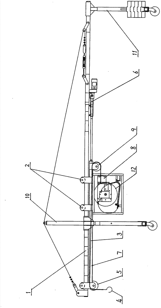
[0039] Such as figure 1 A kind of portable lifting device shown, comprises the suspension beam 1 that is horizontally arranged on the front bracket 10 and the rear bracket 11 and the hoisting mechanism that is arranged on the suspension beam 1, and described hoisting mechanism comprises steel wire rope 3, and described hoisting mechanism also includes A boom 7 that is arranged below the suspension beam 1 and is rollingly connected with the suspension beam 1 through the roller 2, fixed pulley 1 5 is installed on the front end of the boom 7, and fixed pulley 2 9 is installed on the rear end of the boom 7. The boom 7 between the first pulley 5 and the second fixed pulley 9 is fixedly provided with a hoist 8 through the frame, and the front end of the wire rope 3 bypasses the second fixed pulley 9 and the first fixed pulley 5 to connect with the hook 4 successively. The rear end is connected to the cable take-up mechanism 12 installed on the frame by a hoist 8, and the suspension ...

Embodiment 2

[0045] The difference between this embodiment and embodiment 1 is that the cable receiving mechanism 12 is a dynamic cable receiving mechanism, and other structures are the same as in embodiment 1.

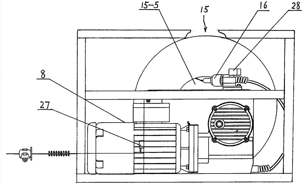
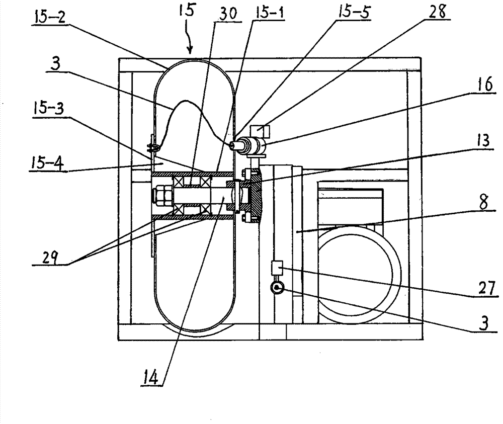
[0046] Figure 4 and Figure 5 Shown is a dynamic cable take-up mechanism, comprising a rotating shaft 18 driven by a hoist 8 and an open cable reel 19 arranged on the rotating shaft 18. One end of the rotating shaft 18 is connected to the hoisting machine 8, and the other end of the rotating shaft 18 passes through a bearing 20 Connected with the frame, the middle part of the rotating shaft 18 is provided with a cable reel connection mechanism 21, the open cable reel 19 is connected with the rotating shaft 18 through the cable reel connection mechanism 21, the open cable reel 19 is provided with a brake 22, the hoist 8 and A guide tube 17 with a wire rope guide head 16 at one end is arranged between the open cable reels 19, one end of the guide tube 17 is rotated on the frame thro...


PUM


Abstract

The invention discloses a portable hoisting device, which comprises a suspension beam and a hoisting mechanism, wherein the suspension beam is horizontally arranged on a front bracket and a rear bracket; the hoisting mechanism is arranged on the suspension beam, and comprises a steel wire rope and a suspension arm; the suspension arm is arranged below the suspension beam, and is in rolling connection with the suspension beam through a roller; a first fixed pulley is arranged at the front end of the suspension arm; a second fixed pulley is arranged at the rear end of the suspension arm; a hoister is fixedly arranged on the suspension arm between the first and second fixed pulleys by a rack; the front end of the steel wire rope sequentially is wound around the first and second fixed pulleys, and is connected with a hanger by rope clip; the rear end of the steel wire rope is connected with a take-up mechanism arranged on the rack by the hoister; a suspension arm driving device connected with the rear end of the suspension arm is also arranged on the suspension beam; and the take-up mechanism is an unpowered take-up mechanism or a powered take-up mechanism. The portable hoisting device has a rational design, a simple structure, high hoisting capability and stable speed, and is convenient to assemble and use.

Description

technical field [0001] The invention relates to the technical field of lifting machinery, in particular to a portable lifting device. Background technique [0002] In the construction of high-rise buildings, after the tower crane is withdrawn, a kind of portable high-rise hoisting device is still needed for material lifting operations. At present, the structural form of the combination of the winch and the lifting device is generally used. The disadvantage of the above structure is that when working at a large height, the weight of the winch will increase rapidly with the increase of the lifting height, thus making the equipment heavy and inconvenient to assemble and transport. Contents of the invention [0003] The object of the present invention is to provide a portable lifting device with simple structure, convenient assembly and strong lifting capacity in view of the deficiencies in the prior art. The hoisting device has a detachable structural form, which is conveni...

Claims


Application Information

Patent Timeline
Patent Type & Authority Patents(China)
IPC IPC(8): B66C23/10B66D3/04B66D3/18
Inventor 王进郑宁舟夏德茂
Owner CHANGAN UNIV
Why Eureka
Try Eureka