Clamping and turning device

A flipping device and clamping technology, which is applied to the lifting device, transmission device, hoisting device, etc., can solve the problems of unsynchronized displacement, inconvenience of clamping and flipping unit 10, etc., and achieve the effect of improving convenience

Inactive Publication Date: 2011-05-25
CHAN LI MACHINERY
View PDF4 Cites 13 Cited by
  • Summary
  • Abstract
  • Description
  • Claims
  • Application Information

AI Technical Summary

Problems solved by technology

The overall displacement of the first plate body 111 and the second plate body 113 cannot be s

Method used


Image

  • Clamping and turning device
  • Clamping and turning device
  • Clamping and turning device

Examples


Embodiment Construction

[0041] Below in conjunction with accompanying drawing, structural principle and working principle of the present invention are specifically described:

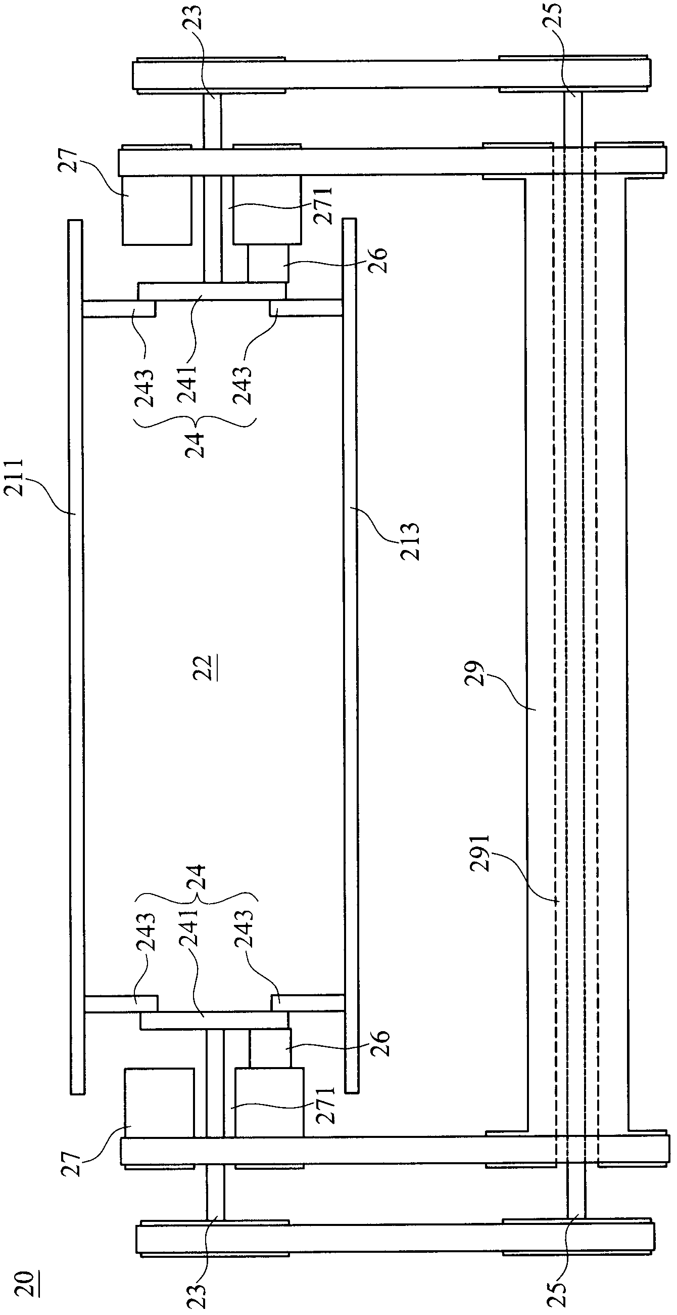
[0042] see figure 2 , is a schematic structural view of an embodiment of the clamping and turning device of the present invention. As shown in the figure, the clamping and turning device 20 includes a first plate body 211, a second plate body 213, two first rod bodies 23, two linkage units 24, two second rod bodies 27, and a third rod body 25 and a fourth rod body 29. The first plate body 211 is disposed opposite to the second plate body 213 , and there is a clamping space 22 between them. When in use, the clamped object (such as stacked fiber products) can be placed in the clamping space 22 , and the clamped object can be clamped and turned over by the first plate body 211 and the second plate body 213 .

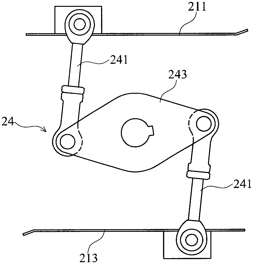
[0043] The two interlocking units 24 respectively include a rotating unit 241 and two connecting units 243 , wherein ...


PUM


Abstract

The invention discloses a clamping and turning device. One ends of two first rod bodies are connected with two ends of a first plate and a second plate through linkage units respectively; while the other end of the first rod bodies are connected with a third rod body; and the third rod body balances rotating angles of the two first rod bodies and the two linkage units, so that the height at the two ends of the first plate and the second plate is kept consistent. One ends of two second rod bodies are connected with the first plate and the second plate respectively, while the other ends of the two second rod bodies are connected with a fourth rod body; and when the fourth rod body rotates, the second rod body is driven to turn the first plate and the second plate. Therefore, two pressing plates can be synchronously opened, closed or turned, while the convenience of the clamping and turning device is favorably improved.

Description

technical field [0001] The invention relates to a clamping and turning device, which can synchronize the opening and closing or turning of two pressure plates, thereby improving the convenience of the clamping and turning device in use. Background technique [0002] see figure 1 , is a schematic diagram of the structure of the existing clamping and turning device. As shown in the figure, the conventional clamping and turning device 10 includes a first board 111 , a second board 113 , two first rods 13 and a second rod 15 . The first board 111 is opposite to the second board 113 , and there is a clamping space 12 between them. [0003] The two first rods 13 are respectively arranged at the two ends of the first plate 111 and the second plate 113, wherein one end of the first rod 13 is respectively connected to the first plate 111 and the second cylinder 171 and the second cylinder 173. Two plate body 113. When the first cylinder 171 and the second cylinder 173 are actuate...

Claims


Application Information

Patent Timeline
IPC IPC(8): B66F19/00F16H37/12
Inventor 许黄彬
Owner CHAN LI MACHINERY
Why Eureka
Try Eureka