Supercharge Your Innovation With Domain-Expert AI Agents!

Complementary slurry distributor of headbox

A pulp distributing device, complementary technology, applied in the direction of textiles and papermaking, paper machine, paper machine wet end, etc., can solve the problem of uneven distribution of pulp, and achieve the effect of simple structure, uniform pulp distribution and good rigidity

Inactive Publication Date: 2011-05-25
SOUTH CHINA UNIV OF TECH
View PDF6 Cites 5 Cited by
  • Summary
  • Abstract
  • Description
  • Claims
  • Application Information

AI Technical Summary

Problems solved by technology

[0003] The purpose of the present invention is to provide a complementary slurry distributor, which overcomes the defect of uneven distribution of slurry in the existing square cone tube slurry distributor of the headbox

Method used


Image

  • Complementary slurry distributor of headbox
  • Complementary slurry distributor of headbox
  • Complementary slurry distributor of headbox

Examples


Embodiment Construction

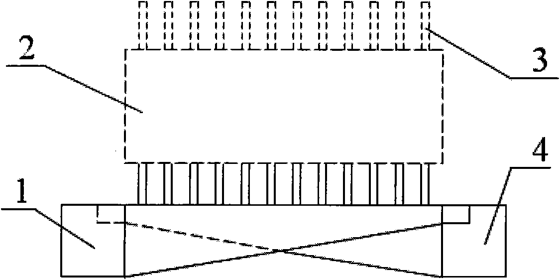
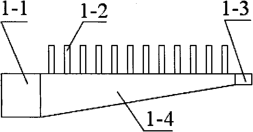
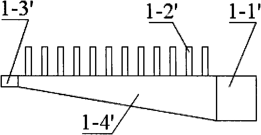
[0015] Such as figure 1 As shown, during installation, the transition pipe 1-1, square cone pipe 14, return pipe 1-3 and branch pipe bundle 1-2 are first assembled into a square cone pipe slurry distributor 1, and the transition pipe 1-1', square cone The pipe 1-4', the return pipe 1-3' and the branch pipe bundle 1-2' are assembled into a square cone tube slurry distributor 4, and then, the square cone tube slurry distributor 1 and 4 are stacked together up and down, left and right symmetrical, They are not connected to each other and are installed at the entrance of the headbox. When working, the pulp passes through the transition pipes 1-1 and 1-1' of the two square cone main pipes arranged symmetrically, and enters into the square cone main pipe 1-4 and 1-4' from the tapered pipe inlet, and the return pulp is fed by two The return port flows out in the opposite direction and enters the stock tank, and the rest of the pulp flows out from the branch tube bundles 1-2 and 1-2'...


PUM


Abstract

The invention discloses a complementary slurry distributor of a headbox. The complementary slurry distributor is characterized by consisting of two step diffuser heads stacked up and down together in a complementary mode, wherein the step diffuser heads are symmetrical left and right and are not mutually communicated. Therefore, the complementary slurry distributor realizes complementation of slurry mass flow of two square cone header pipes and corresponding branch pipe bundles by skillfully using the characteristic of non-uniform slurry distribution of single step diffuser head, and can obtain good slurry distribution performance after the slurry passes through a slurry stabilizing chamber. The complementary slurry distributor has the advantages of simple structure, good rigidity and uniform slurry distribution.

Description

technical field [0001] The invention relates to the headbox technology of a high-speed paper machine, in particular to a complementary pulp distributor of the headbox. Background technique [0002] At present, the headbox of a high-speed paper machine is mainly composed of a pulp distributor, a pulp stabilization chamber, a turbulence generator and a lip shrinkage area. The pulp distributor is the first part of the headbox. The chamber is connected, and the slurry stabilization chamber is combined with the lip constriction area through the turbulence generator. Its working process is as follows: the pulp enters the pulp distributor from the pulp feeding pump, enters the pulp stabilization chamber through the pulp distribution tube bundle, and after passing through the turbulent flow generator, the uniform pulp suspension enters the lip shrinkage area stably, and then sprays on the net. It can be seen that the pulp distribution performance of the pulp distributor directly af...

Claims


Application Information

Patent Timeline
IPC IPC(8): D21F1/04
Inventor 陈克复刘伟李军
Owner SOUTH CHINA UNIV OF TECH
Features
  • R&D
  • Intellectual Property
  • Life Sciences
  • Materials
  • Tech Scout
  • Unparalleled Data Quality
  • Higher Quality Content
  • 60% Fewer Hallucinations
Learn More