Tool wear monitoring system capable of realizing self-learning in numerical control machining state

A tool wear and processing state technology, applied in the field of tool wear measurement of CNC machine tools, can solve the problems of affecting the normal processing of the machine tool, changing the structure of the machine tool, and inconvenient operation, so as to achieve real-time monitoring of tool wear status, improve the application range, and facilitate communication.

Inactive Publication Date: 2011-05-25
HUAZHONG UNIV OF SCI & TECH +1
View PDF10 Cites 85 Cited by
  • Summary
  • Abstract
  • Description
  • Claims
  • Application Information

AI Technical Summary

Problems solved by technology

The method based on volume loss characteristics requires downtime detection, which takes man-hours and makes it difficult to achieve online real-time monitoring
Acoustic emission, vibration and other methods are inconvenient for signal monitoring, troublesome sensor installation, affecting the normal processing of the machine tool, and even need to change the structure of the machine tool, so it can only be used in laboratory research, and it is difficult to apply to actual production
The method of monitoring the cutting torque and indexing the tool state through the power feature can only be applied to the finishing condition with fixed cutting parameters.
However, in actual mass production, the cutting parameters of rough machining fluctuate within a certain range and are not fixed values, so they cannot be used
The above-mentioned sensor-based monitoring methods basically use independent signal monitoring and processing modules, which do not make full use of the existing information of the machine tool, and because they are independent modules, they are not embedded in the CNC system, and an independent module is required for operation. Hardware processing, increased cost, inconvenient operation

Method used


Image

  • Tool wear monitoring system capable of realizing self-learning in numerical control machining state
  • Tool wear monitoring system capable of realizing self-learning in numerical control machining state
  • Tool wear monitoring system capable of realizing self-learning in numerical control machining state

Examples


Embodiment Construction

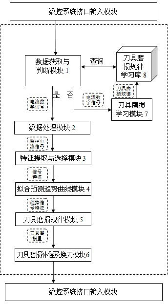
[0016] The monitoring system provided by the present invention obtains the machine tool drive motor current signal and the machine tool tool processing information obtained from the numerical control system, goes through a series of signal processing and feature extraction selection processes, and finally monitors the tool wear amount to realize the monitoring of tool wear. Monitor VB, and feed back the monitoring results to the CNC system, and the CNC system responds accordingly according to the wear of the tool, prompting to change the tool or change the tool compensation amount.

[0017] Such as figure 1 As shown, the monitoring system includes data acquisition and judgment module 1, data processing module 2, feature extraction and selection module 3, fitting prediction trend curve module 4, tool wear rule module 5, tool wear compensation and tool change module 6, tool wear Learning module 7 and tool wear law learning library 8.

[0018] The tool wear law learning library ...


PUM


Abstract

The invention discloses a tool wear monitoring system capable of realizing self-learning in a numerical control machining state. The structure of the system is that: a tool wear rule learning library stores learned tool wear rules; a data acquisition and judgment module provides a servo drive current digital signal for a data processing module to perform format conversion and store the signal as a monitoring current signal; a characteristic extraction and selection module selects signal characteristics strongly correlated with tool wear; a fitted predicted trend curve module establishes a signal characteristic-tool machining service life relationship curve; a tool wear rule module obtains the learned tool wear rules from the tool wear rule learning library, and substitutes the trend signal characteristics into the learned tool wear rules to obtain a tool wear extent; and a tool wear compensation and tool replacement module makes a tool wear compensation and tool replacement decision according to the tool wear extent, and provides the tool wear compensation and tool replacement decision for a numerical control system interface input module. The system is applied to the condition offluctuating cutting parameters in mass production, and can achieve relatively higher accuracy under the condition of constant cutting parameters.

Description

technical field [0001] The invention belongs to the field of tool wear measurement of numerical control machine tools, and is an online and real-time monitoring system for tool wear status embedded in a numerical control system. Background technique [0002] Over the years, scholars at home and abroad have done a lot of work in the online monitoring of tool wear, and have achieved remarkable results in the fields of monitoring methods, monitoring parameter selection, and signal processing and identification. Some methods have been used in production. The traditional tool wear state monitoring method is based on the relevant characteristics of the tool volume loss, and directly obtains the tool wear value through contact measurement or CCD imaging. For example, see the Chinese patent application number: CN200910031737.9, and the title of the invention is: CNC milling tool wear measurement method based on shape replication, which copies the shape of the tool on the copy materi...

Claims


Application Information

Patent Timeline
Patent Type & Authority Applications(China)
IPC IPC(8): G05B19/406
Inventor 李斌刘红奇毛新勇丁玉发彭芳瑜毛宽民
Owner HUAZHONG UNIV OF SCI & TECH
Why Eureka
Try Eureka