Label detection and dynamic load optimization method for ultrahigh-frequency RFID reader

A technology of dynamic optimization, reader, applied in the direction of instruments, electromagnetic radiation induction, inductive record carriers, etc., can solve the problems of high heat generation of the working power amplifier circuit, inability to effectively adapt to the working environment, and high technical requirements, and achieve dynamic load distribution. Reasonable, conducive to long-term stable work and the effect of reducing technical difficulty

Inactive Publication Date: 2011-05-25
上海实甲智能科技股份有限公司
View PDF3 Cites 16 Cited by
  • Summary
  • Abstract
  • Description
  • Claims
  • Application Information

AI Technical Summary

Problems solved by technology

[0004] The existing fixed load working mode of the reader has the following disadvantages: 1. The load distribution is unreasonable: during use, no matter whether there is a tag in the radiation range of the antenna, the fixed load is used to work, resulting in the unlabeled antenna card reading time Too long will waste energy; if the load setting is too small, the effect of identifying tags will not be good; if the load setting is too large, the power amplifier circuit will heat up too much for a long time, and the stability of the reader will decline; 2. The label recognition efficiency is low: Unlabeled antennas may take too long to read cards and waste time, while tagged antennas wait for too long to read cards, and the efficiency of tag recognition is low; 3. Poor adaptability to the site environment: users need to deploy reasonable rest time according to the site conditions parameters, the technical requirements for users are too high, and it is difficult to find a reasonable parameter when multiple antennas are deployed, which cannot effectively adapt to various on-site working environments

Method used


Image

  • Label detection and dynamic load optimization method for ultrahigh-frequency RFID reader
  • Label detection and dynamic load optimization method for ultrahigh-frequency RFID reader
  • Label detection and dynamic load optimization method for ultrahigh-frequency RFID reader

Examples


Embodiment Construction

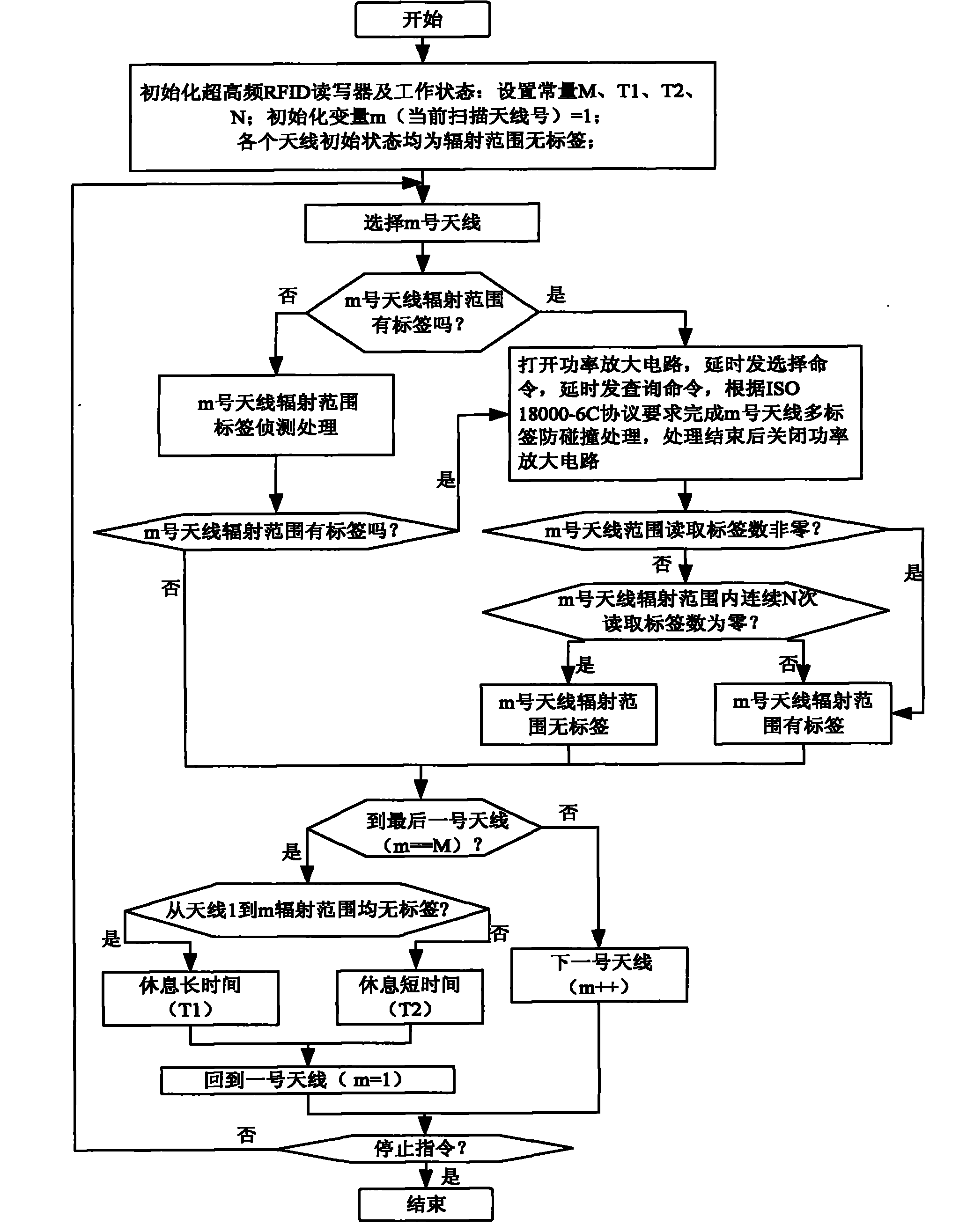
[0030] Below in conjunction with accompanying drawing, take ISO 18000-6C (a kind of ultra-high frequency radio frequency identification international standard agreement) agreement in conjunction with four antenna reader-writers as an example to specifically describe the embodiment of the present invention, the ultra-high frequency RFID reader-writer includes baseband processing and radio frequency There are two parts in the front end. The RF front end generally includes a radio frequency transmitting circuit, a radio frequency receiving circuit and an antenna. The radio frequency transmitting circuit includes a power amplifier circuit. The antenna includes an antenna switching circuit and an antenna connection port. labels such as figure 1 As shown, the tag detection and load dynamic optimization method of the UHF RFID reader of the present invention will figure 1 After instantiating relevant parameters in , implement the following steps:

[0031]Step 1, initialize the UHF RF...


PUM


Abstract

The invention discloses a label detection and dynamic load optimization method for an ultrahigh-frequency radio frequency identification (RFID) reader. The method comprises the following nine steps: S1, initializing the ultrahigh-frequency RFID reader and the working state, wherein an antenna number is M, the frequency for continuously reading that no labels exist in aerial radiation ranges is N, the break time of the reader when no labels exist is T1, the break time of the reader when labels exist is T2, and T1 is greater than T2; setting that no labels exist in the initial states in all aerial radiation ranges, wherein the number of the currently scanned antenna is m, and the antennae are scanned from an antenna No.1; and S2, selecting the antenna No.m, judging labels exist in the radiation range of the antenna No.m, if so, entering the step S5, otherwise, entering the step S3. The load distribution of the reader is dynamically optimized by detecting whether the labels exist in the aerial radiation range so as to improve label identification efficiency in all antenna ranges, dynamically adapt to fieldwork environment, and reduce technological difficulty of reader deployment.

Description

technical field [0001] The present invention relates to a UHF RFID (Radio Frequency Identification, radio frequency identification) reader, in particular to a tag detection and load dynamic optimization method for a UHF RFID reader. Background technique [0002] Radio frequency identification technology is a technology that uses radio frequency to carry out non-contact two-way communication to achieve the purpose of identifying targets and exchanging data, and realizes automatic identification and management of various objects in different states; it has small size, capacity Large, long life, reusable, etc., can support fast reading and writing, non-visual identification, mobile identification, multi-target identification, positioning and long-term tracking management, so it has a huge market in logistics, manufacturing, retail and other fields. The working frequency of UHF RFID is between 860MHz and 960MHz. When working, the radio frequency tag is located in the far field a...

Claims


Application Information

Patent Timeline
Patent Type & Authority Applications(China)
IPC IPC(8): G06K7/00G06K7/10
Inventor 柳林林王斌陈家能仲海洋张倍刘宝昌张鸣岐张德卿
Owner 上海实甲智能科技股份有限公司
Why Eureka
Try Eureka