Method for manufacturing electrolytic capacitor

一种电解电容器、制造方法的技术,应用在电解电容器制造、电解电容器、电容器等方向,能够解决配置引线端子困难等问题

Active Publication Date: 2011-05-25
PANASONIC INTPROP MANAGEMENT CO LTD
View PDF4 Cites 8 Cited by
  • Summary
  • Abstract
  • Description
  • Claims
  • Application Information

AI Technical Summary

Problems solved by technology

As mentioned above, it becomes more difficult to arrange the lead terminals according to the specification when there are multiple terminals arranged

Method used


Image

  • Method for manufacturing electrolytic capacitor
  • Method for manufacturing electrolytic capacitor
  • Method for manufacturing electrolytic capacitor

Examples


Embodiment approach 1

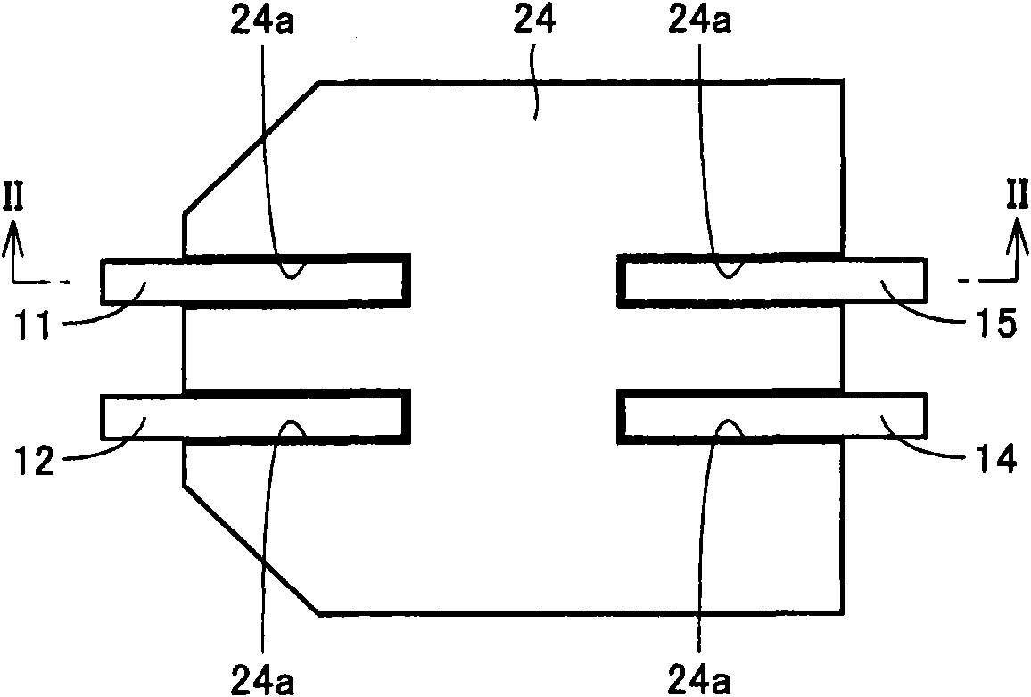
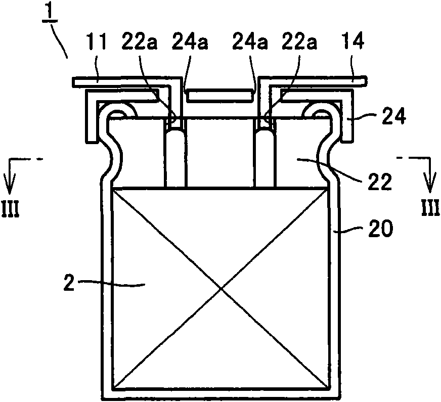
[0047] refer to Figure 1 ~ Figure 3 , The solid electrolytic capacitor of this embodiment has a capacitor element 2, a seat plate 24, an aluminum case 20, a sealing rubber seal 22, and four electrode lead terminals.

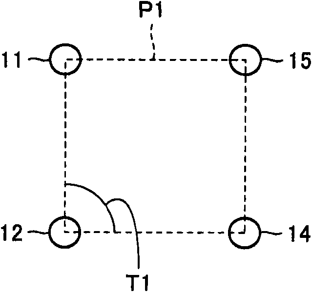
[0048] The above four electrode lead terminals are composed of first and second anode lead joint terminals (anode lead terminals) 11 , 12 and first and second cathode lead joint terminals (cathode lead terminals) 14 , 15 . And, the four terminals are connected with the quadrilateral P1 ( image 3 ) are mounted on the capacitor element 2 at positions corresponding to the four vertices. Preferably, the angle T1 of the quadrilateral P1 has an angle within 90°±20°, more preferably, the quadrilateral P1 is substantially rectangular, and still more preferably, the quadrilateral P1 is substantially square.

[0049] Next, a method of manufacturing the solid electrolytic capacitor of this embodiment will be described.

[0050] refer to Figure 4, prepare the terminal...

Embodiment approach 2

[0065] refer to Figure 17 ~ Figure 19 , The solid electrolytic capacitor of this embodiment has three electrode lead terminals. The three electrode lead terminals are composed of first and second anode lead joint terminals (anode lead terminals) 11 and 12 and a cathode lead joint terminal (cathode lead terminal) 13 . In addition, the three terminals are in contact with the triangle P2 ( Figure 19 ) are mounted on the capacitor element 2 at positions corresponding to the three vertices. It is preferable that the angle T2 of the triangle P2 has an angle of 60°±20°, and it is more preferable that the triangle P2 is a substantially equilateral triangle.

[0066] In addition, since the structure other than the above is substantially the same as the structure of the said Embodiment 1, the same code|symbol is attached|subjected to the same or corresponding element, and repeated description is not repeated.

[0067] Next, a method of manufacturing the solid electrolytic capacitor...

Embodiment approach 3

[0081] In Embodiment 1, the winding core 31 ( Image 6 , Figure 7 ).

[0082] refer to Figure 29 and Figure 30 , in this embodiment, instead of the winding core 31, the winding core 33 is prepared. One end portion of the axis AX of the winding core 33 is divided into first and second portions 33a and 33b by the slit SL. Additionally, if Figure 30 As shown, the section of the core 33 perpendicular to the axis AX has an outer edge corresponding to a substantially circular shape Q3. In addition, the cross-section of the winding core 33 mentioned here is a cross-section which does not consider the existence of the slit SL.

[0083] refer to Figure 31 , the respective one ends of the anode foil 3 , the cathode foil 4 , and the separator papers 5 and 6 are sandwiched between the slits SL. Next, if Figure 29 ~ Figure 31 As shown by the arrow R of the arrow, the winding core 33 is rotated around the axis AX. Thus, the separator paper 6 , the anode foil 3 , the separato...


PUM


Abstract

The invention provides a method for manufacturing electrolytic capacitors. Electrode lead terminals in a number not less than three are attached to a cathode foil and an anode foil. The electrode lead terminals include at least one cathode lead terminal attached to the cathode foil and at least one anode lead terminal attached to the anode foil. A winding core having an axis is prepared. The cathode foil and the anode foil are wound around the winding core, being overlapped each other. A cross section of the winding core perpendicular to the axis includes an outer edge having a portion along each side of a polygon with the above number of sides. Thereby, a method for manufacturing an electrolytic capacitor capable of suppressing displacement of a lead terminal can be provided.

Description

technical field [0001] The present invention relates to a method of manufacturing an electrolytic capacitor, and more particularly to an electrolytic capacitor having wound anode foil and cathode foil. Background technique [0002] As one form of the electrolytic capacitor, there is an electrolytic capacitor formed by winding an anode foil and a cathode foil each having a lead terminal attached thereto. As such a capacitor, a capacitor having one anode lead terminal and one cathode lead terminal, that is, a capacitor having a total of two lead terminals, is widely used at present. [0003] However, in recent years, reductions in equivalent series inductance (ESL: Equivalent Series Inductance) and equivalent series resistance (ESR: Equivalent Series Resistance) have been required. Therefore, for example, as shown in Japanese Patent Application Laid-Open No. 2004-179621, a solid electrolytic capacitor having more than two terminals is also used. [0004] Due to the dispersio...

Claims


Application Information

Patent Timeline
Patent Type & Authority Applications(China)
IPC IPC(8): H01G9/00H01G9/04
CPCH01G9/0029Y10T29/43
Inventor 川久保哲哉中尾广信
Owner PANASONIC INTPROP MANAGEMENT CO LTD
Why Eureka
Try Eureka