
Electrical switch

A technology for switches and electric loads, applied in the field of switches, can solve problems such as low elasticity, hard-to-contact chamber compression, etc.

Inactive Publication Date: 2011-05-25
TE CONNECTIVITY GERMANY GMBH
View PDF5 Cites 31 Cited by
  • Summary
  • Abstract
  • Description
  • Claims
  • Application Information

AI Technical Summary

Problems solved by technology

However, ceramic materials have only low elasticity, which means that cost-effective press-in or snap-in connections cannot be used
It is also difficult to compress the contact chamber, as is often the case with highly loaded switches

Method used


Image

  • Electrical switch
  • Electrical switch
  • Electrical switch

Examples


Embodiment Construction

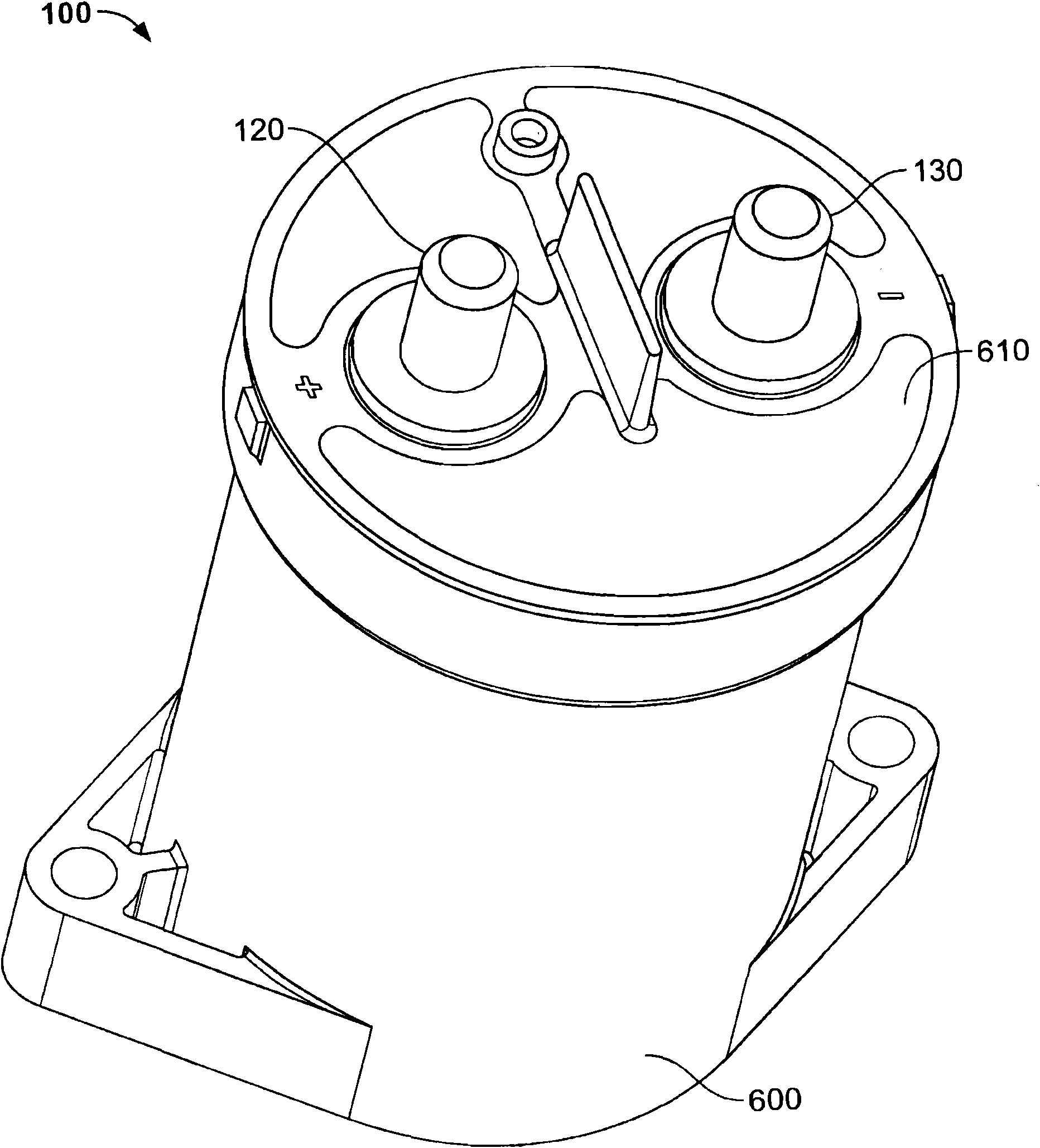
[0032] figure 1 is a perspective view of a switch 100 for switching electrical loads. The switch 100 may also be referred to as a relay or a contactor. The switch 100 includes a housing 600 having a dome 610 . Housing 600 and dome 610 may comprise a plastic material or another material.

[0033] The first contact member 120 and the second contact member 130 are guided through two apertures into the dome 610 . The first contact member 120 and the second contact member 130 comprise an electrically conductive material, such as metal, and are arranged as electrical contacts connected to an electrical load to be switched, such as an electric motor.

[0034] The switch 100 is provided to open and close the electrical connection between the first contact member 120 and the second contact member 130 . In this way, the switch 100 can be used, for example, to switch the power supply to a motor. When it is turned off, for example at a voltage exceeding 850V, a high current exceeding...


PUM


Abstract

A switch for switching an electrical load comprises a contact chamber in which a first contact member, a second contact member and a movable contact bridge are arranged. The contact chamber is arranged in a mounting support. The contact chamber comprises a ceramic material and the mounting support comprises a plastics material.

Description

technical field [0001] The invention relates to a switch for switching an electrical load according to the preamble of claim 1 . Background technique [0002] Switches for opening and closing electrical connections are known from a number of arrangements in the prior art. Contactors and relays are used to switch high and very high electrical loads. This type of switch includes a contact chamber, which places high demands on the arc chamber in terms of possible operating temperatures, permissible internal pressure, electrical insulation capacity and arc resistance. [0003] Conventionally, contact chambers of this type are manufactured from plastic materials, resulting in advantages in terms of production and assembly. For example, the elastic properties of plastic materials can be used to create press-fit or other elastic connections. However, the thermal resistance and electrical insulation capabilities of plastic materials are limited. The flame impingement caused by t...

Claims


Application Information

Patent Timeline
IPC IPC(8): H01H1/20H01H50/54
CPCH01H9/443H01H1/24H01H51/29H01H50/546H01H50/023H01H50/02H01H50/20H01H50/04
Inventor 拉尔夫·霍夫曼马塞厄斯·克罗克尤多·加贝尔
Owner TE CONNECTIVITY GERMANY GMBH
Features
  • Generate Ideas
  • Intellectual Property
  • Life Sciences
  • Materials
  • Tech Scout
  • Unparalleled Data Quality
  • Higher Quality Content
  • 60% Fewer Hallucinations
Learn More