Charger structure

A charger and circuit board technology, applied in the direction of secondary battery charging/discharging, secondary battery repair/maintenance, etc., can solve the problem of limiting power supply or ground wiring line width, increasing the design difficulty of designers, electronic noise interference, etc. problems, to achieve the effect of shortening production man-hours, reducing design man-hours, and reducing costs

Inactive Publication Date: 2011-05-25
C TECH UNITED
View PDF0 Cites 1 Cited by
  • Summary
  • Abstract
  • Description
  • Claims
  • Application Information

AI Technical Summary

Problems solved by technology

[0013] Furthermore, because the circuit board 70 needs to dig out the opening 71 with a large area, the circuit wiring on the circuit board 70 must be concentrated in some specific areas, so it is easy to cause electronic noise such as crosstalk (crosstalk). Interference is generated; moreover, the wiring width of power supply or grounding is also limited, which greatly increases the design difficulty of designers, resulting in the extension of design man-hours

Method used


Image

  • Charger structure
  • Charger structure
  • Charger structure

Examples


Embodiment Construction

[0041] According to the technical means of the present invention, the specific embodiments suitable for the present invention are enumerated below, and are described in conjunction with the drawings as follows:

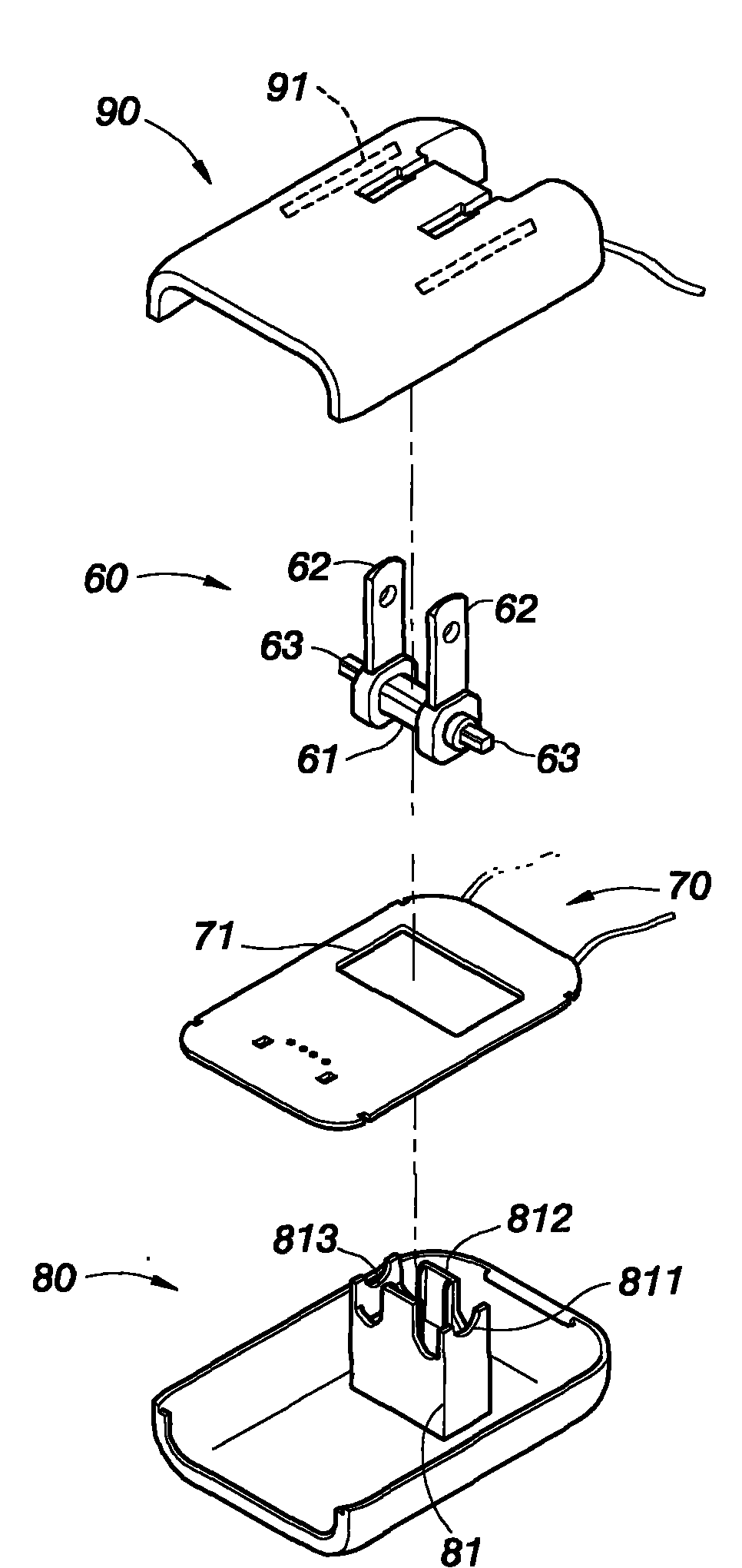
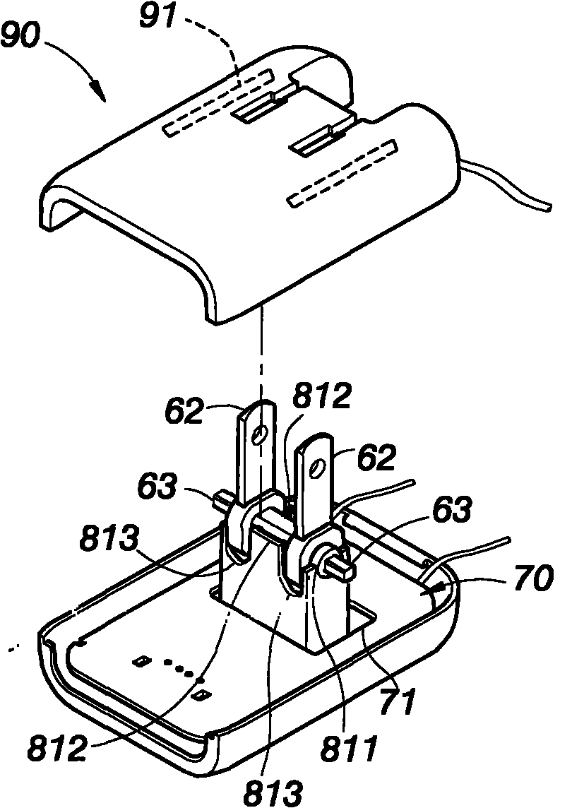
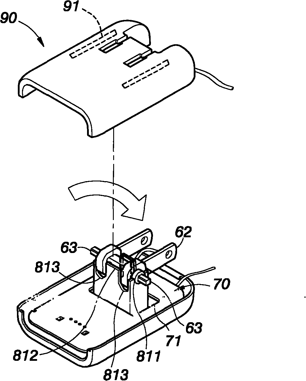
[0042] Such as Figure 4 , Figure 5 As shown, a "charger structure" of the present invention includes a first housing 10, a second housing 20, a circuit board 30 arranged between the first and second housings 10, 20, a positioning Cover plate 40, and a plug unit 50, wherein:

[0043] The first housing 10 is provided with a receiving plate 11, and the receiving plate 11 is provided with a positioning column 12 opposite to the second housing 20, and the positioning column 12 can be installed by the aforementioned positioning cover 40 It is inserted and positioned at the same time, and the storage plate 11 is provided with a storage space 13 that can accommodate the aforementioned plug unit 50 on the other side of the positioning column 12, and the first housing 10 is...


PUM


Abstract

The invention relates to a charger structure which can simplify design difficulty and reduce manufacturing cost. The charger structure comprises a first shell body, a second shell body, a positioning cover board which is arranged between the first shell body and the second shell body, a plug unit and a circuit board, wherein a positioning column is arranged on the first shell body, and the positioning cover board can be used for the inserting and the positioning of the positioning column; a spacing column is arranged on the second shell body, the spacing column penetrates the bottom of the circuit board to butt the positioning cover board at a smaller area, further, the positioning cover board generates spacing effects on the plug unit, and segment positioning efficacy is generated when the plug unit rotates. Compared with the traditional charger which is provided with a segment rotating plug unit, the invention not only can reduce the design difficulty of the circuit board but also achieve the effect of reducing the manufacturing cost.

Description

technical field [0001] The invention relates to a charger structure for a mobile phone, in particular to a charger structure that can simplify design man-hours and reduce material costs. Background technique [0002] A mobile phone is a very common electronic communication product in modern life, and when the mobile phone is in use, a charger must be connected to a power source to charge the battery in the mobile phone to provide the power required for the normal operation of the mobile phone. [0003] The plug end of the charger usually includes a body and a group of protruding body power plug terminals that can be inserted into the socket, and, for the convenience of carrying around, the power plug terminals are usually rotated to facilitate When in use, it can be stored in the main body, so as to avoid the inconvenience of carrying due to the protruding power plug terminals from the main body. [0004] Although the design of the rotating power plug terminal at the plug e...

Claims


Application Information

Patent Timeline
Patent Type & Authority Applications(China)
IPC IPC(8): H01M10/44
CPCY02E60/12Y02E60/10
Inventor 李昌雄
Owner C TECH UNITED
Why Eureka
Try Eureka