Convenient method for controlling direction of rotation of synchronous motor of single-phase permanent magnet and motor using same

A technology of synchronous motor and rotation direction, applied in the direction of electronic commutator, electrical components, electromechanical devices, etc., can solve the problem of uncertain steering of synchronous motor, and achieve the effect of simple and practical control method, high reliability and low cost

Inactive Publication Date: 2011-05-25
艾如菊
View PDF5 Cites 22 Cited by
  • Summary
  • Abstract
  • Description
  • Claims
  • Application Information

AI Technical Summary

Problems solved by technology

[0006] The technical problem to be solved by the present invention is to avoid the disadvantages of the above-mentioned prior art and provide a convenient method for controlling the rotation direction of a single-phase permanent magnet synchronous motor, a single-phase permanent magnet synchronous motor provided with a steering control circuit, and a single-phase permanent magnet synchronous motor for single-phase The steering control circuit of the phase permanent magnet synchronous motor, the convenient method and the steering control circuit cleverly solve the problem of uncertain steering of the synchronous motor by means of each hardware module, and can reliably ensure that the synchronous motor runs in the set direction , has the advantages of simple and practical control method, simple control circuit, low cost, high reliability, strong anti-interference and can effectively reduce thyristor switching noise.

Method used


Image

  • Convenient method for controlling direction of rotation of synchronous motor of single-phase permanent magnet and motor using same
  • Convenient method for controlling direction of rotation of synchronous motor of single-phase permanent magnet and motor using same
  • Convenient method for controlling direction of rotation of synchronous motor of single-phase permanent magnet and motor using same

Examples


Embodiment 1

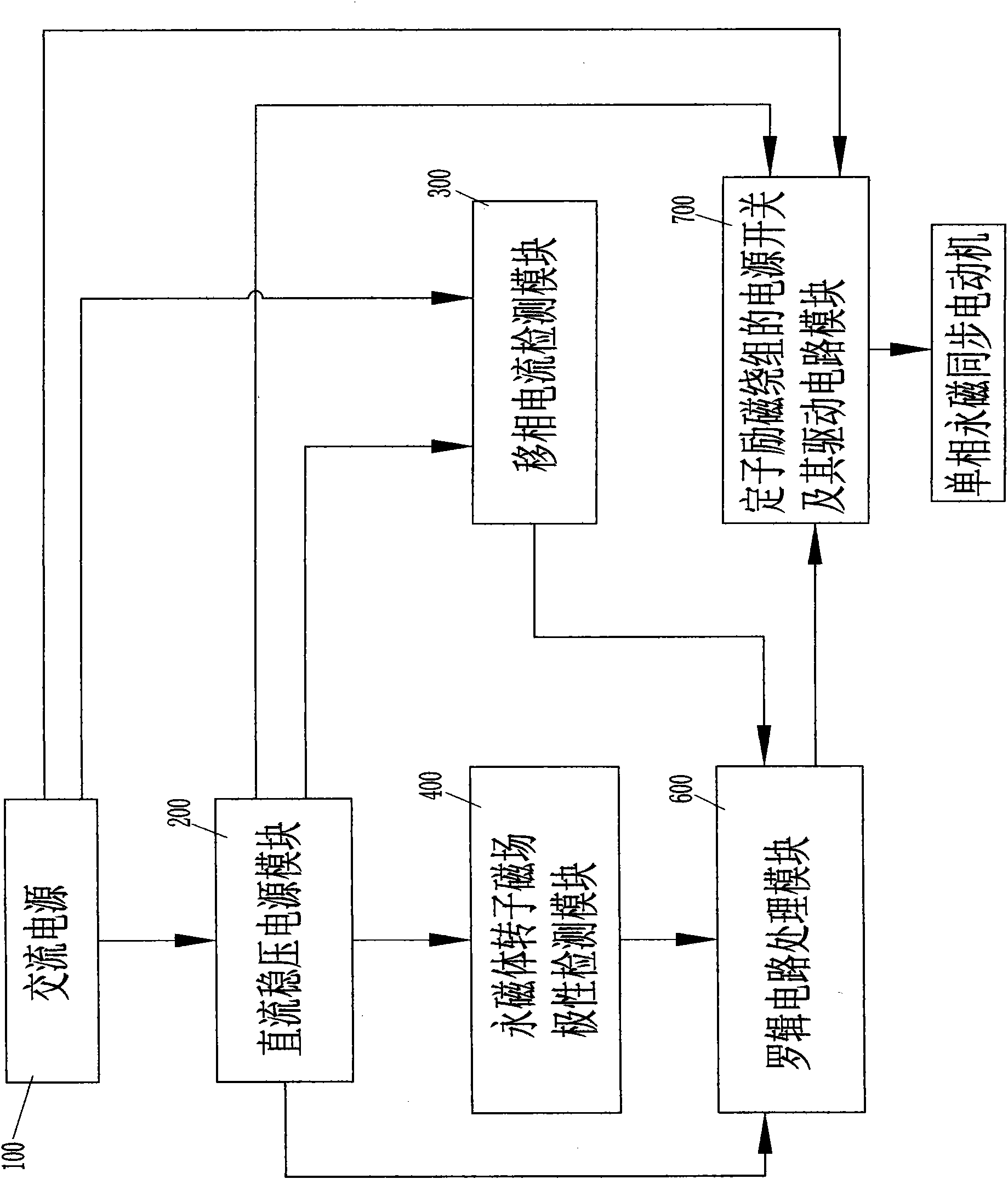
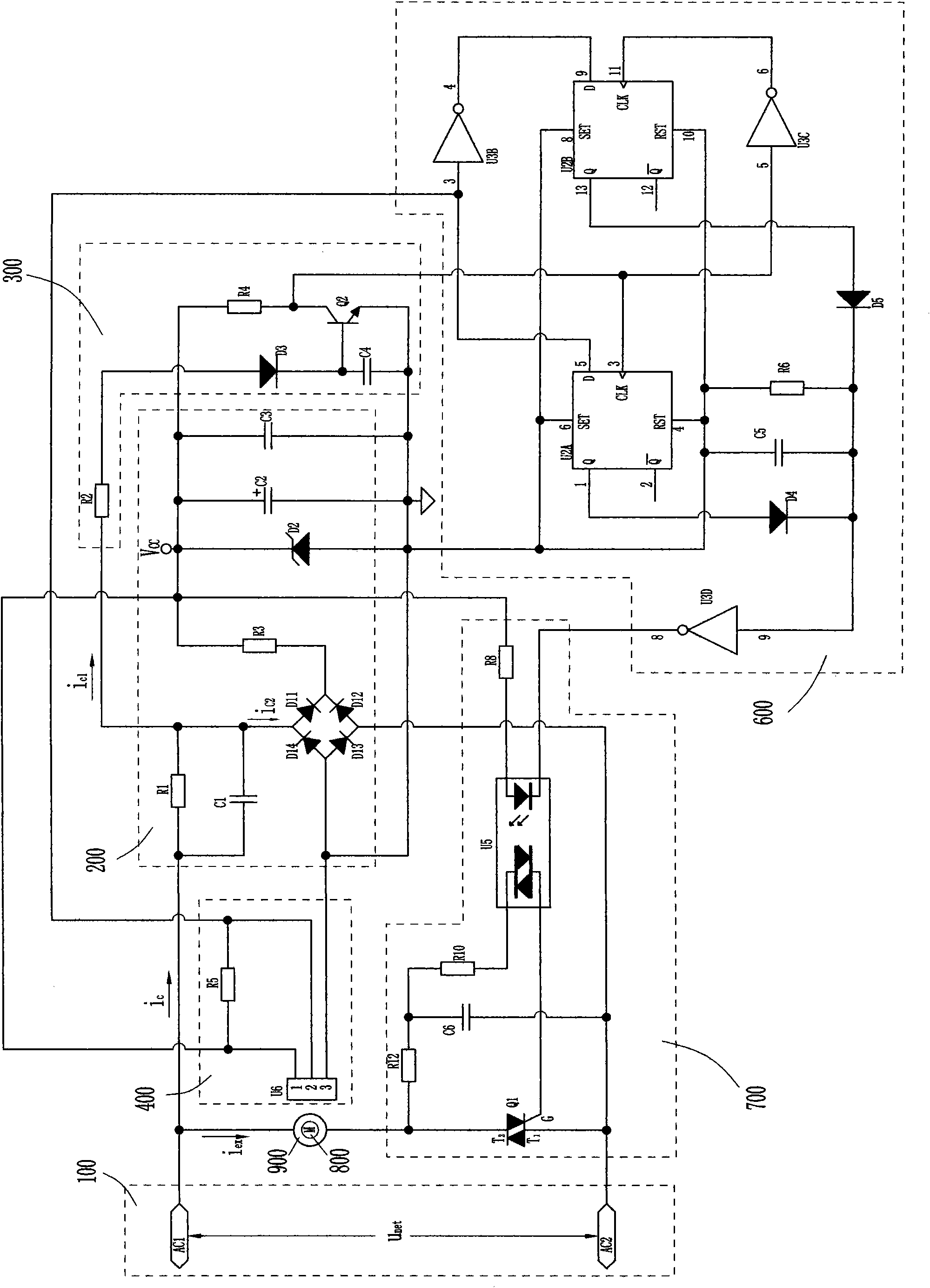
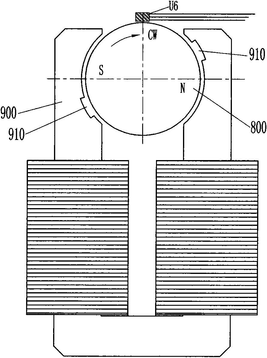
[0066] see figure 1 and figure 2, a single-phase permanent magnet synchronous motor provided with a steering control circuit is manufactured through the above-mentioned convenient method for controlling the rotation direction of a single-phase permanent magnet synchronous motor, including a permanent magnet rotor 800 with a pair of magnetic poles and a field winding wound Stator 900; the single-phase permanent magnet synchronous motor also includes a steering control circuit that reliably ensures that the single-phase permanent magnet synchronous motor rotates in a set direction, and the steering control circuit includes a DC stabilized power supply module 200, a phase shifting The current detection module 300, the permanent magnet rotor magnetic field polarity detection module 400, the logic circuit processing module 600 and the power switch of the stator excitation winding and its drive circuit module 700, and input to the DC stabilized power supply module 200, phase-shift ...

Embodiment 2

[0076] see Figure 10 and Figure 11 , which is basically the same as the preferred embodiment 1, the difference is that:

[0077] A motor running direction selection module 500 is added, which is a double-pole double-throw switch SW1, and is electrically connected to the permanent magnet rotor magnetic field polarity detection module 400 and the logic circuit processing module 600 respectively.

[0078] see Figure 11 , a movable contact 1 of the double-pole double-throw switch SW1 is electrically connected to the D input terminal of the D flip-flop U2A of the logic circuit processing module 600, that is, the input pin 5, and the other movable contact 2 is electrically connected to the logic circuit processing module 600. The D input terminal of the D flip-flop U2B of the module 600 is electrically connected to the input pin 9; corresponding to the moving contact 1 are two static contacts 3 and 4, and corresponding to the moving contact 2 are two static contacts Points 5 a...


PUM


Abstract

The invention provides a convenient method for controlling direction of rotation of a synchronous motor of a single-phase permanent magnet. The method comprises the following steps: A. arranging a power switch of stator exciting current and ensuring the power switch to conform to the following requirements: when a rotor of the permanent magnet is motionless, the power switch is conducted after the power voltage is connected, or after the rotor of the permanent magnet rotates, the power switch is conducted if the direction of rotation conforms to the set requirement, or after the rotor of the permanent magnet rotates, the power switch is turned off if the direction of rotation is opposite to the set requirement, and when the rotor of the permanent magnet only shakes or wriggles, the power switch is conducted; B. arranging a permanent magnet rotor field polarity sensing device obtaining the real-time field polarity of the permanent magnet rotor in designated position; and C. using the simplest sequential logical circuit to complete each judgment in the step A, thus implementing control of the direction of rotation of the rotor of the permanent magnet. The invention has the advantages of simple and practical control method, simple control circuit, low cost, high reliability, strong interference resistance, capability of effectively reducing the noises of thyristor switches, etc.

Description

【Technical field】 [0001] The invention relates to a synchronous motor with permanent magnets, in particular to a synchronous motor with stationary armatures and rotating magnets, and in particular to a control circuit for the rotation direction of a single-phase permanent magnet synchronous motor. 【Background technique】 [0002] As we all know, single-phase AC synchronous or asynchronous motors produce pulsating magnetic fields because they only have one-phase power supply. The pulsating magnetic field can be decomposed into two rotating magnetic field components that are equal in size and opposite in direction, so they have no starting torque. For small or miniature single-phase permanent magnet synchronous motors, in fact, as long as the rotor shakes at the moment the stator excitation winding is powered on, it can keep rotating in a certain direction, because the rotating magnetic field generated by the rotor rotation weakens until it cancels the stator The opposite compo...

Claims


Application Information

Patent Timeline
Patent Type & Authority Applications(China)
IPC IPC(8): H02P6/14H02P6/16H02K29/08
Inventor 不公告发明人
Owner 艾如菊
Why Eureka
Try Eureka