Supercharge Your Innovation With Domain-Expert AI Agents!

Vacuum switching tube

A vacuum switching tube and steam technology, applied in the direction of electric switches, high voltage/high current switches, high voltage air circuit breakers, etc., can solve the problems of large structure shape, inconvenient use, expensive manufacture, etc., to improve the compressive strength, facilitate Assembly effect

Inactive Publication Date: 2011-05-25
SIEMENS AG
View PDF6 Cites 2 Cited by
  • Summary
  • Abstract
  • Description
  • Claims
  • Application Information

AI Technical Summary

Problems solved by technology

However, when the distance between the vacuum interrupters is increased in this way, a large structural shape or construction volume that is inconvenient to use and expensive to manufacture results.

Method used


Image

  • Vacuum switching tube
  • Vacuum switching tube
  • Vacuum switching tube

Examples


Embodiment Construction

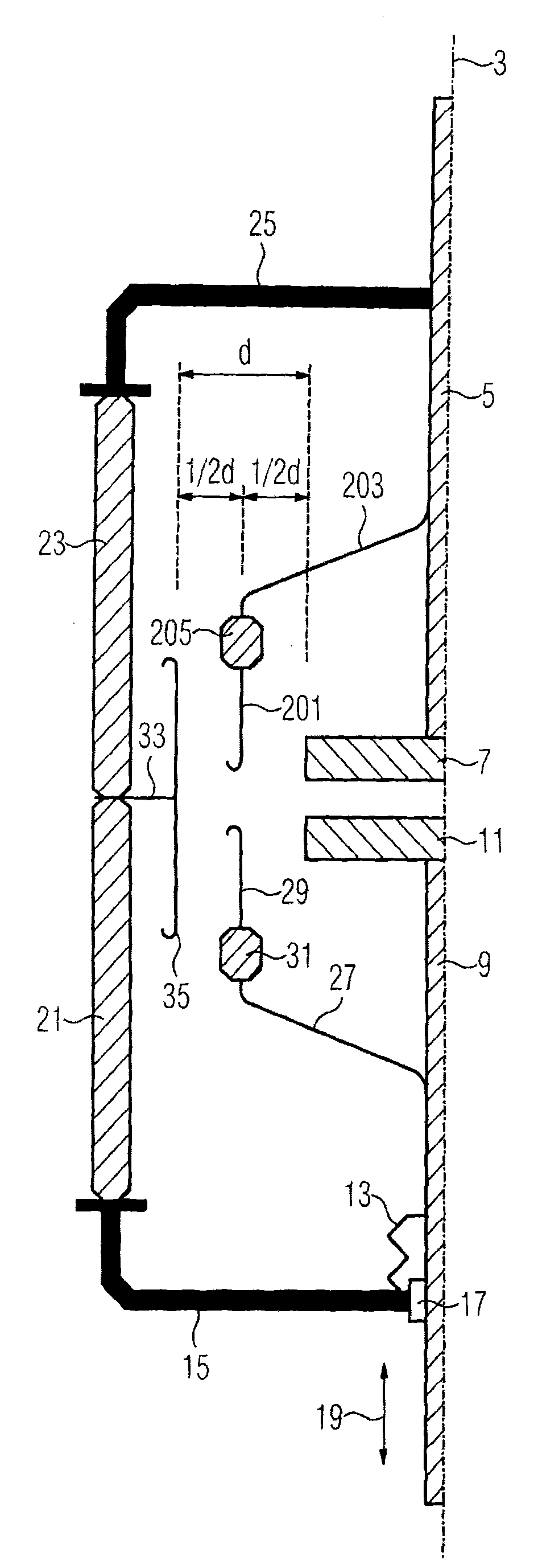
[0025] exist figure 1 A sectional view of an embodiment of a vacuum interrupter 1 envisaged according to the invention is shown in . Only one half of the vacuum interrupter is shown here in a sectional view, the other half being designed symmetrically with respect to the axis of symmetry or the axis of rotation 3 . The vacuum interrupter 1 has a fixed or stationary stem 5 which carries a first (static) contact 7 . A second (moving) contact 11 is fastened on the axially movable stem 9 . The axially displaceable stem 9 is connected to the metal cover 15 in an axially displaceable and vacuum-tight manner by means of an elastic bellows 13 . Such a metal cover 15 has a slide bearing 17 in which the axially displaceable stem 9 is guided. The axial movement that the moving contact rod 9 can carry out is represented by a double-headed arrow 19 .

[0026] The metal cover 15 is connected to a first insulating member 21 which has a hollow cylindrical shape and is composed of ceramics...


PUM


Abstract

The invention relates to a vacuum switching tube comprising a first contact piece (7) disposed on a fixed contact bolt (5), a second contact piece (11) disposed on an axial moving contact bolt (9) and a first vapor shield (29) made of an electrically conductive material for protecting the inner surfaces of a housing of the vacuum switching tube from metal vapor depositions. The first vapor shield (29) is held at one of the contact bolts (9) and is electrically insulated against this contact bolt (9).

Description

technical field [0001] The invention relates to a vacuum switch tube, which has a first contact arranged on a stationary stem, a second contact arranged on an axially moving stem, and a contact made of a material with electrical conductivity. A first vapor shield for protecting the inner surface of the vacuum interrupter housing from metal vapor deposition. Background technique [0002] Such a vacuum interrupter is known from German laid-open patent document DE 2633543 A1. [0003] The requirement for vacuum interrupters is to reliably switch high currents at high voltages. In this case, when the vacuum interrupter is disconnected, not only must the withstand voltage be provided with respect to the distance between the two contacts, but also other electrically conductive parts (such as electrically conductive housing parts or made of electrically conductive The compressive strength of the spacing between the steam shields composed of materials. In all these distances (vac...

Claims


Application Information

Patent Timeline
IPC IPC(8): H01H33/66
CPCH01H33/66261H01H2033/66276H01H2033/66292
Inventor 乌尔夫·舒曼
Owner SIEMENS AG
Features
  • R&D
  • Intellectual Property
  • Life Sciences
  • Materials
  • Tech Scout
  • Unparalleled Data Quality
  • Higher Quality Content
  • 60% Fewer Hallucinations
Learn More