Light emitting element driving circuit

A technology for light-emitting components and driving circuits, applied in circuits, electrical components, electroluminescent light sources, etc., can solve problems such as brightness deviation and LED characteristic deviation, and achieve the effects of reducing current stress, prolonging life, and preventing overcurrent from flowing through.

Inactive Publication Date: 2011-05-25
SHARP KK
View PDF3 Cites 17 Cited by
  • Summary
  • Abstract
  • Description
  • Claims
  • Application Information

AI Technical Summary

Problems solved by technology

However, since the characteristics of LEDs vary, the luminance of LEDs varies even when driven with a constant current.

Method used


Image

  • Light emitting element driving circuit
  • Light emitting element driving circuit
  • Light emitting element driving circuit

Examples


no. 1 approach

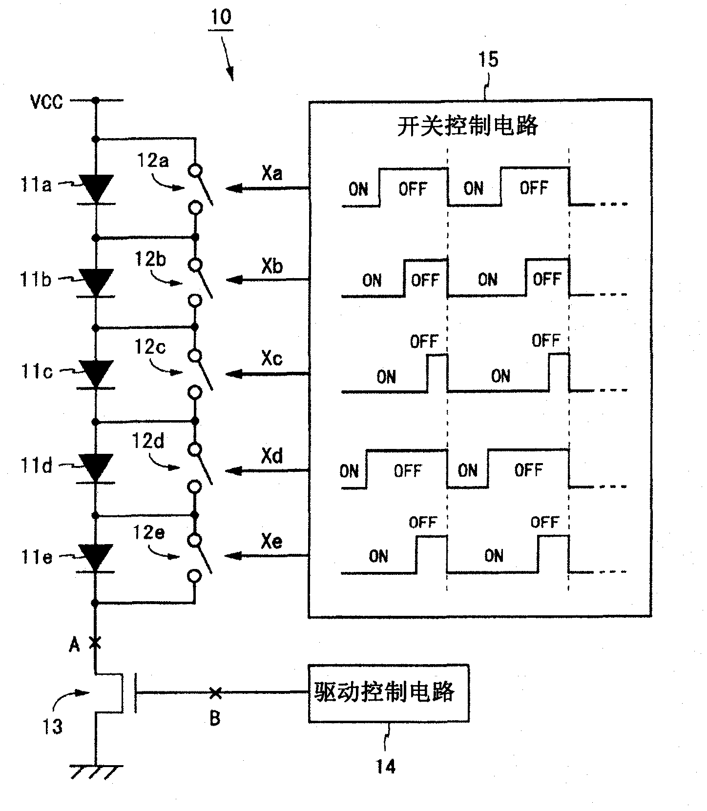
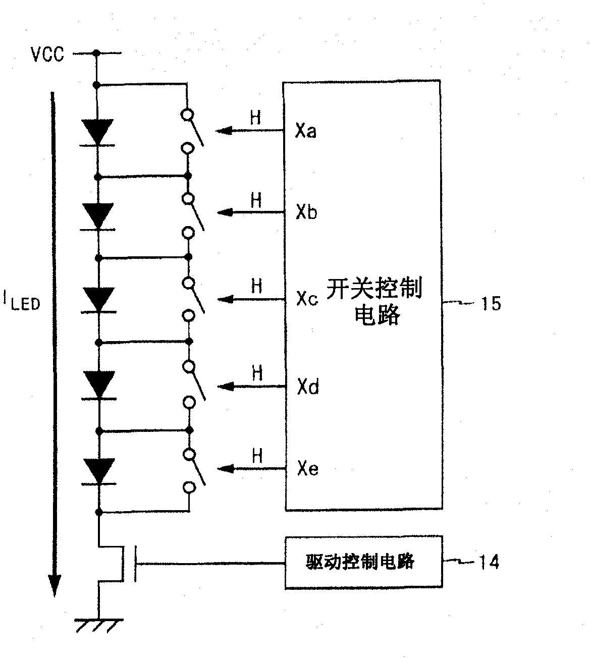
[0048] figure 1 It is a block diagram showing the configuration of the LED drive circuit according to the first embodiment of the present invention. figure 1 The shown LED drive circuit 10 includes switches 12a-12e, FET13, drive control circuit 14 and switch control circuit 15, and drives LEDs 11a-11e with a constant current. In addition, five LEDs are driven by the LED driving circuit 10 here, but the number of LEDs driven by the LED driving circuit 10 may be arbitrary as long as it is two or more. In other words, the LED drive circuit 10 that drives two or more LEDs has effects described later.

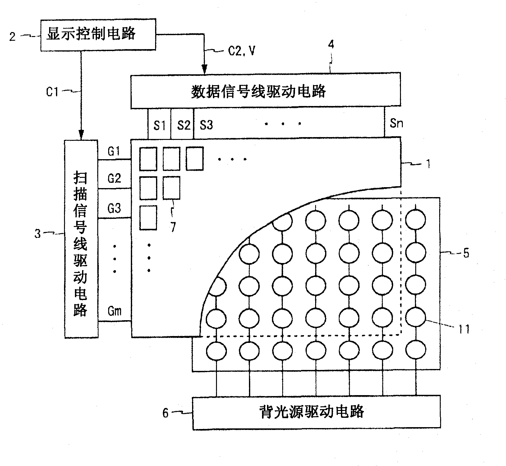
[0049] Before describing the LED drive circuit 10 in detail, refer to figure 2 An example of how to use the LED drive circuit 10 will be described. figure 2 It is a block diagram showing the configuration of a liquid crystal display device including the LED drive circuit 10 . figure 2 The shown liquid crystal display device includes a liquid crystal panel 1 , a display cont...

no. 2 approach

[0065] Figure 6 It is a block diagram showing the configuration of the LED drive circuit according to the second embodiment of the present invention. Figure 6 The LED driving circuit 20 shown is obtained by combining the LED driving circuit 10 ( figure 1 ) is formed by replacing the drive control circuit 14 and the switch control circuit 15 with the drive control circuit 24 and the switch control circuit 25. Among the constituent elements of the present embodiment, the same elements as those of the first embodiment are denoted by the same reference numerals, and description thereof will be omitted.

[0066] Like the drive control circuit 14, the drive control circuit 24 controls the gate voltage of the FET 13 so that the amount of drive current matches a predetermined target value. The switch control circuit 25 individually controls the on and off of the switches 12a to 12e like the switch control circuit 15, and changes all the switches 12a to 12e from the off state to t...


PUM


Abstract

The present invention provides a light emitting element driving circuit, wherein a plurality of LEDs (11a-11e) are connected in series, and an FET (13) which functions as a constant current source is arranged on one end. Switches (12a-12e) are connected in parallel to the LEDs (11a-11e). A switch control circuit (15) separately controls to turn on / off the switches (12a-12e) by using switch control signals (Xa-Xe), and changes the states of all the switches (12a-12e) in the same timing from the off-sate to the on state. The drive control circuit (14) may control the gate voltage of the FET (13) to a low level in timing when the switches (12a-12e) change to the on-state. Thus, luminances of the light emitting elements (LEDs) are separately adjusted and an overcurrent is prevented from flowing to the light emitting elements.

Description

technical field [0001] The present invention relates to a light-emitting element driving circuit, in particular to a light-emitting element driving circuit for constant current driving of a plurality of light-emitting elements connected in series. Background technique [0002] As a backlight for a liquid crystal display device, an LED backlight in which a plurality of LEDs (Light Emitting Diodes: light emitting diodes) are arranged two-dimensionally may be used. In the LED backlight, in order to keep the brightness of the backlight constant, a method of connecting a plurality of LEDs in series, setting a constant current source at one end, and driving the LEDs with a constant current is used. However, since the characteristics of LEDs vary, the luminance of LEDs varies even when driven with a constant current. Therefore, in order to suppress variations in the luminance of LEDs, an LED drive circuit having a function of individually adjusting the luminance of LEDs has been d...

Claims


Application Information

Patent Timeline
Patent Type & Authority Applications(China)
IPC IPC(8): H01L33/00H05B37/02H05B44/00
CPCG09G3/3426G09G2330/025G09G2320/0233H05B33/083G09G2320/064H05B45/48
Inventor 中泽健山元学
Owner SHARP KK
Why Eureka
Try Eureka