Supercharge Your Innovation With Domain-Expert AI Agents!

Filter device

A filtering device and pixel technology, applied in television, electrical components, digital video signal modification, etc., can solve the problems of image quality degradation, inability to interpolate, filtering processing technology can not become filtering processing, etc. The effect of deterioration of image quality

Inactive Publication Date: 2011-05-25
SHARP KK
View PDF4 Cites 16 Cited by
  • Summary
  • Abstract
  • Description
  • Claims
  • Application Information

AI Technical Summary

Problems solved by technology

That is, the filter processing technique described in Non-Patent Document 1 cannot be a realistic method for filter processing for a block of a larger size than the prior art
[0034] In addition, the filter processing method described in Patent Document 1 is a method of performing interpolation without considering the original pixel value of the pixel to be processed as the target of the filter processing. will not be able to interpolate properly
Therefore, there is still a problem of image quality degradation in the decoded image that has been filtered.

Method used


Image

  • Filter device
  • Filter device
  • Filter device

Examples


Embodiment approach 1

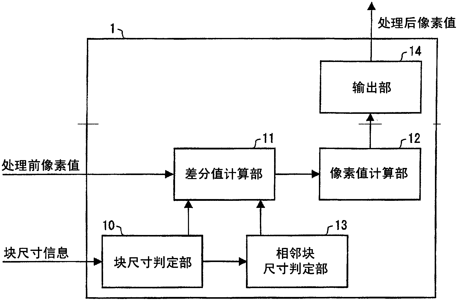
[0088] One embodiment of the filtering device of the present invention is regarded as Embodiment 1, and the following refers to Figure 1-14 Be explained. The filter device of the present invention is used to eliminate block noise generated when decoding image data (image information) divided into a plurality of blocks and encoded. Such block noise is particularly noticeable at the boundaries of adjacent blocks. Therefore, the filtering device of the present invention performs filtering processing for removing block noise from processing target pixels located in the vicinity of block boundaries.

[0089] (Configuration of filter device 1)

[0090] figure 1 The configuration of the filter device 1 in this embodiment is shown. figure 1 It is a block diagram showing the configuration of main parts of the filter device 1 . Such as figure 1 As shown, the filter device 1 takes as input the pixel value before filtering (pixel value before correction), and outputs the pixel val...

Embodiment approach 2

[0295] (Configuration of Image Decoding Device 100 )

[0296] Regarding the image decoding device including the filtering device of the present invention, as Embodiment 2, refer to the following Figure 15 Be explained. Figure 15 It is a block diagram showing the configuration of main parts of the image decoding device 100 according to the second embodiment. In addition, since the same code|symbol is attached|subjected to the same member as Embodiment 1, the description is abbreviate|omitted.

[0297] Such as Figure 15 As shown, the image decoding device 100 includes: a variable length code decoding unit 101 , an inverse quantization / inverse transformation unit 102 , a predicted image generation unit 103 , a frame storage unit 104 , a block size management unit 105 , and the filtering device 1 . As components other than the filter device 1 in the image decoding device 100 , the same components as those of the conventional image decoding device can be used.

[0298] Herei...


PUM


Abstract

A filter device (1) comprises a differential value calculation unit (11) for calculating the absolute value of the differential between the pixel value of a boundary pixel in a block to be processed having a block size is not smaller than a first threshold value and the pixel value of an adjacent pixel adjacent to the boundary pixel, and a pixel value calculation unit (12) whereby the post-filtration pixel value of a pixel to be processed, which is positioned near the boundary between the block to be processed and an adjacent block, is calculated on the basis of the pre-filtration pixel value of the pixel to be processed and the pixel value of the adjacent pixel when the calculated differential absolute value is smaller than a second threshold value. It is thereby possible to provide a filter device for preventing degradation of image quality of a decoded image while suppressing an increase in the amount of calculation depending on the block size by which the image is divided.

Description

technical field [0001] The present invention relates to a filter (Filter) device for eliminating block noise generated when decoding image information divided into blocks (Blocks) of different sizes and encoded. Background technique [0002] Image coding technology is used in various imaging devices around us, from TVs to mobile phones that can perform image processing. [0003] In the field of image coding technology, generally speaking, image data (image information) is divided into multiple blocks, orthogonal transformation is performed in units of divided blocks, and the obtained transformation coefficients are quantized. Above, coding is performed by variable length coding of the quantized transform coefficients. According to such an encoding method, since information is lost during quantization, image degradation occurs. In particular, since large distortion (ie, block noise) is generated at the boundary of each block which is a unit in which orthogonal transform is ...

Claims


Application Information

Patent Timeline
Patent Type & Authority Applications(China)
IPC IPC(8): H04N7/26
CPCH04N7/26058H04N19/00278H04N19/00139H04N7/26244H04N19/00066H04N7/26122H04N7/26888H04N19/00909H04N19/117H04N19/136H04N19/176H04N19/86
Inventor 猪饲知宏
Owner SHARP KK
Features
  • R&D
  • Intellectual Property
  • Life Sciences
  • Materials
  • Tech Scout
  • Unparalleled Data Quality
  • Higher Quality Content
  • 60% Fewer Hallucinations
Learn More