Method and ultrasonic imaging device for distinguishing artery and vein

An ultrasonic imaging and equipment technology, applied in ultrasonic/sonic/infrasonic diagnosis, application, sonic diagnosis and other directions, can solve the problems of anesthesiologist's difficulties, and achieve the effect of easy viewing of pictures, simplified workflow, and great convenience

Inactive Publication Date: 2011-06-01
GE MEDICAL SYST GLOBAL TECH CO LLC
View PDF4 Cites 28 Cited by
  • Summary
  • Abstract
  • Description
  • Claims
  • Application Information

AI Technical Summary

Problems solved by technology

But this requires doctors to have a lot of experience in accurately identifying arteries and vein

Method used


Image

  • Method and ultrasonic imaging device for distinguishing artery and vein
  • Method and ultrasonic imaging device for distinguishing artery and vein
  • Method and ultrasonic imaging device for distinguishing artery and vein

Examples


Embodiment Construction

[0039] Hereinafter, embodiments of the present invention will be described in detail with reference to the drawings. The present invention is not limited to the embodiments.

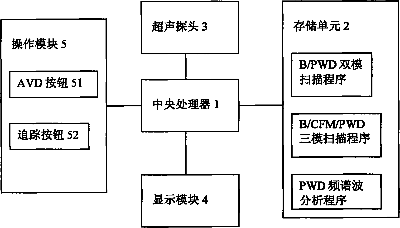
[0040] The method for identifying arteries and veins in B-mode or CFM-mode images provided by the present invention, which is applied to medical ultrasound imaging equipment, simplifies the traditional complex workflow of arterial and vein identification. Such as figure 2 As shown, it is a functional module schematic diagram of the ultrasonic imaging device of the present invention, which includes a central processing unit 1, a storage unit 2, an ultrasonic probe 3, a display module 4, and an operating module 5, wherein the central processing unit 1 receives the ultrasonic probe 3, operates The information or instructions of the module 5 are processed accordingly, and the processed results are displayed by the display module 4 or stored in the storage unit 2. Wherein, the operation module 5 includes a...


PUM


Abstract

The invention provides an ultrasonic imaging device, comprising a central processing unit, a storage cell, an ultrasonic probe, a display module and an operating module, wherein the operating module comprises an artery and vein distinguishing button, a B/pulse wave Doppler (B/PWD) dual-mode scanning program, a pulse wave Doppler (PWD) frequency spectrum wave analysis program and/or B/colour flow mapping/pulse wave Doppler (B/CFM/PWD) three-mode scanning program are stored in the storage cell. When the artery and vein distinguishing button is pressed down, the central processing unit receives an artery and vein distinguishing instruction, the display module is controlled to display a tracking range, the tracking range is moved to select a blood vessel to be captured, the central processing unit calls a corresponding frequency spectrum wave analysis program from the storage cell to analyze the captured blood vessel according to the received artery and vein distinguishing instruction and a captured blood vessel echo signal, whether the capture blood vessel is an artery or vein is judged, an identification is marked on the capture blood vessel according to the judging result, and the identification is displayed by virtue of the display module.

Description

technical field [0001] The invention relates to the field of medical ultrasound imaging, in particular to a method for identifying arteries and veins in B mode or Color Flow Mapping (CFM) images in ultrasound imaging and an ultrasound imaging device. Background technique [0002] Existing B-mode technology can display blood vessels, but sometimes it is difficult to identify blood vessels from images of sound-absorbing tissues such as cysts. Thus, Color Flow Mapping (CFM for short) appeared, which can help clinicians to easily identify blood vessels from non-vascular tissues. CFM uses Doppler technology to encode the direction information and velocity information of the blood flow and superimpose the obtained encoded information on the B-mode image to obtain the flow image of the blood vessel. For color flow images, red represents that the flow direction of blood vessel flow is towards the probe, and blue represents away from the probe. For those experienced clinicians, the...

Claims


Application Information

Patent Timeline
IPC IPC(8): A61B8/00A61B8/06A61B8/14
Inventor 吴方刚
Owner GE MEDICAL SYST GLOBAL TECH CO LLC
Why Eureka
Try Eureka