Method for forming large complex thin-wall shell with circumferential inner ribs

A thin-walled shell and forming belt technology, which is applied to the field of large and complex thin-walled shells with annular inner ribs of forming belts, can solve the problems of high cost, complicated spinning process, and difficulty in changing molds and adjusting molds.

Active Publication Date: 2011-06-01
NORTHWESTERN POLYTECHNICAL UNIV
View PDF4 Cites 37 Cited by
  • Summary
  • Abstract
  • Description
  • Claims
  • Application Information

AI Technical Summary

Problems solved by technology

[0003] In order to overcome the deficiencies in the prior art, such as many molds, complex spinning process, long production cycle, high cost, and difficulty in changing molds and adjusting molds, the present invention proposes a method for forming large complex thin-walled shells with rings facing inward. method

Method used


Image

  • Method for forming large complex thin-wall shell with circumferential inner ribs
  • Method for forming large complex thin-wall shell with circumferential inner ribs
  • Method for forming large complex thin-wall shell with circumferential inner ribs

Examples


Embodiment 1

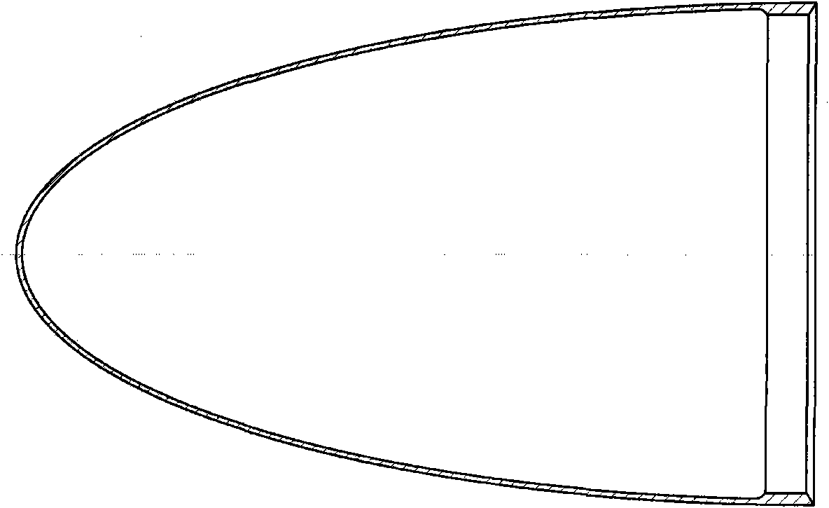
[0048] This embodiment is a large-scale complex thin-walled shell with ring-shaped inward ribs at the mouth of a certain spacecraft. The shape of the part is as follows: figure 1 As shown, the material is 3A21, the thickness of the non-rib part is t=1.5mm, and the maximum wall thickness of the rib part is t max = 4.35 mm. Specific steps are as follows:

[0049] Step 1, determine the blank size;

[0050] Take the thickness allowance Δt=0.65mm, according to the formula (1), the thickness t of the slab 1 is obtained 0 = 5mm.

[0051] t 0 = t max +Δt (1)

[0052] In formula (1), t 0 is the thickness of slab 1, t max is the maximum thickness of the rib part of the spinning part, Δt is the thickness allowance, and Δt=0.5~1.0mm.

[0053] According to the part drawing, the volume of the part is determined to be 448186mm 3 , considering the machining allowance ΔD = 62mm, substituting into the formula (2) to get the diameter D of the slab 1 0 = 400mm.

[0054] ...

Embodiment 2

[0086] This embodiment is a large-scale complex thin-walled shell with ring-shaped inward ribs at the mouth of a certain spacecraft. The shape of the part is as follows: figure 1 As shown, the material is 3A21, the thickness of the non-rib part is t=1.5mm, and the maximum wall thickness of the rib part is t max = 4.35 mm. Specific steps are as follows:

[0087] Step 1, determine the blank size;

[0088] Take the thickness allowance Δt=0.5mm, according to the formula (1), the thickness t of the slab 1 is obtained 0 = 4.85 mm.

[0089] t 0 = t max +Δt (1)

[0090] In formula (1), t 0 is the thickness of slab 1, t max is the maximum thickness of the rib part of the spinning part, Δt is the thickness allowance, and Δt=0.5~1.0mm.

[0091] According to the part drawing, the volume of the part is determined to be 448186mm 3 , considering the machining allowance ΔD = 50mm, substituting into the formula (2) to get the diameter D of the slab 1 0 = 393mm.

[0092] ...

Embodiment 3

[0124] This embodiment is a large-scale complex thin-walled shell with ring-shaped inward ribs at the mouth of a certain spacecraft. The shape of the part is as follows: figure 1 As shown, the material is 3A21, the thickness of the non-rib part is t=1.5mm, and the maximum wall thickness of the rib part is t max = 4.35 mm. Specific steps are as follows:

[0125] Step 1, determine the blank size;

[0126] Take the thickness allowance Δt=1.0mm, according to the formula (1), the thickness t of the slab 1 is obtained 0 = 5.35 mm.

[0127] t 0 = t max +Δt (1)

[0128] In formula (1), t 0 is the thickness of slab 1, t max is the maximum thickness of the rib part of the spinning part, Δt is the thickness allowance, and Δt=0.5~1.0mm.

[0129] According to the part drawing, the volume of the part is determined to be 448186mm 3 , considering the machining allowance ΔD = 70mm, substituting into the formula (2) to get the diameter D of the slab 1 0 = 397mm.

[0130] ...


PUM


Abstract

The invention relates to a method for forming a large complex thin-wall shell with circumferential inner ribs. The large complex thin-wall shell with the circumferential inner ribs is formed by adopting a composite spinning method combining strong spinning and general spinning. The method comprises the steps of: in forming, firstly determining the radius of an initial position to be ribbed on a plate blank, the height of the head of a filmed spin-forming part and the axial distance between a final ribbed position of a spinning piece and the top end of the spinning piece, and then forming by composite spinning in multiple rounds. In the method, under the conditions that only one core die and one set of rotary wheels are adopted, a prefabricated blank is not needed, intermediate annealing phase does not need to be adopted and no subsequent machining is needed, due to adoption of a reasonable composite spinning process, the flat plate blank is spun to form the large complex thin-wall shell with the circumferential inner ribs, so that the forming period is shortened, the cost is reduced, and large amount of manpower resources, material resources and financial resources are saved. The invention provides scientific basis for the spin-forming process scheme of the large complex thin-wall shell with the circumferential inner ribs and the determination of tracks of the rotary wheels, which is beneficial to promotion of further development of the advanced theory and technology of spinning.

Description

technical field [0001] The invention belongs to the field of spinning forming, and in particular relates to a method for forming a large complex thin-walled shell with rings facing inward. Background technique [0002] In the field of aerospace and weapons, such as figure 1 The large-scale and complex curved generatrix thin-walled shell with ring-shaped inward ribs at the mouth has very broad application requirements and prospects. Since the shape of this kind of parts is a complex curved generatrix configuration and the mouth taper angle is close to zero, and the inner shape has ring-to-inward ribs, the shape is complex and the precision is high, so the processing and manufacturing is difficult. Based on the finite element simulation software ABAQUS, Zhou Qiang and others established a three-dimensional finite element model for the strong spinning of conical parts with annular inward ribs (Zhou Qiang, Zhan Mei, Yang He. Finite element analysis of the spinning stress and st...

Claims


Application Information

Patent Timeline
Patent Type & Authority Applications(China)
IPC IPC(8): B21D22/14
Inventor 詹梅杨合蒋华兵陈飞
Owner NORTHWESTERN POLYTECHNICAL UNIV
Why Eureka
Try Eureka