Rotor for a wind power plant

A technology of wind power generation equipment and rotors, which is applied in the control of wind power generators, wind power generation, wind power generators, etc. It can solve the problems that maintenance personnel are difficult to access the drive, and achieve the effects of easy maintenance, easy access, and cost saving

Active Publication Date: 2011-06-01
SSB WIND SYST
View PDF6 Cites 0 Cited by
  • Summary
  • Abstract
  • Description
  • Claims
  • Application Information

AI Technical Summary

Problems solved by technology

In previous designs, the drive with the screw mechanism supported on the rotor hub had a large

Method used


Image

  • Rotor for a wind power plant
  • Rotor for a wind power plant
  • Rotor for a wind power plant

Examples


Embodiment Construction

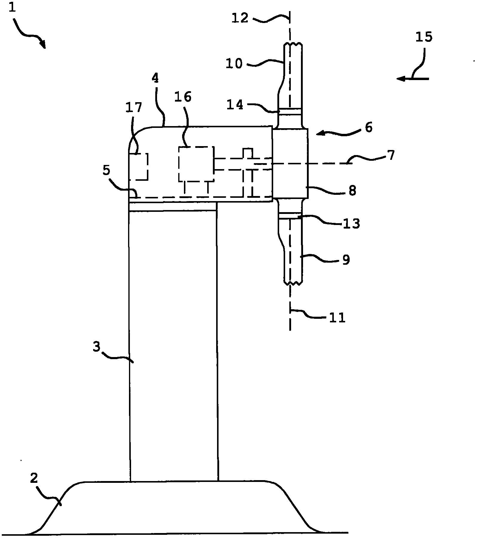
[0028] Depend on figure 1 A wind power plant 1 is shown in which a tower 3 rising from a foundation 2 is connected at its end facing away from the foundation 2 to a machine room 4 . The machine room 4 comprises a machine frame 5 on which a rotor 6 is mounted rotatably about a rotor axis 7 and has a rotor hub 8 and connected thereto rotor blades 9 and 10 which are respectively rotatable around them. The blade axis 11 or 12 rotates relative to the rotor hub 8 . The rotor blades 9 and 10 are each mechanically coupled to a blade angle adjustment drive 13 or 14 , by means of which the individual rotor blades can be rotated about the associated blade axis. The rotor 6 is rotatable by the wind 15 about the rotor axis 7 and is mechanically coupled to a generator 16 which is fixed on the machine frame 5 and is arranged in particular in the machine room 4 . For controlled operation of the wind power plant 1 , a wind power plant control device 17 is provided, by means of which wind pow...


PUM


Abstract

The invention relates to a rotor for a wind power plant having a rotor hub (8), at least one rotor blade (9) rotatably mounted around a blade axis (11) on the rotor hub (8) and at least one threaded spindle mechanism (13) which is switched between the rotor hub (8) and the rotor blade (9) and connected both to the rotor hub (8) and the rotor blade (9) and which is rotatable around the blade axis (11) relative to the rotor hub (8) by actuating the threaded spindle mechanism (13), having a spindle nut (32), a threaded spindle (31) and a drive (21) which is mounted in the region of the transition between the rotor hub (8) and the rotor blade (9) on the rotor blade (9) and can be rotated together therewith around the blade axis (11).

Description

technical field [0001] The invention relates to a rotor for a wind power plant with a rotor hub, at least one rotor blade mounted on the rotor hub rotatably about the blade axis and at least one screw mechanism connected between the hub and the rotor Between the blades, and connected to both the rotor hub and the rotor blade, the rotor blade can rotate relative to the rotor hub around the blade axis by manipulating a screw mechanism, the screw mechanism has a screw nut, a screw and a driver. Background technique [0002] Such rotors are described in German patent applications 102008055473.1 and 102009045467.5. In previous designs, the drive of the screw mechanism mounted on the rotor hub has a large distance from the rotor blades, so that access to the drive is difficult for maintenance personnel. Even the drive part is arranged outside the inner space of the rotor hub, so besides being more inaccessible, measures against lightning strikes and other weather influences must ...

Claims


Application Information

Patent Timeline
IPC IPC(8): F03D1/06F03D7/02F03D9/00
CPCY02E10/723Y02E10/721F03D7/0224F05B2260/79Y02E10/72F03D1/06F03D7/02
Inventor 法比奥·伯托洛蒂
Owner SSB WIND SYST
Why Eureka
Try Eureka